Flow-through consumable anodes

a consumable anode and flow-through technology, applied in the direction of electrolysis processes, electrolysis devices, cells, etc., can solve the problems of unfavorable chlorine gas evolution, health and safety risks, rapid deterioration of electrolyte, etc., and achieve the effect of avoiding disintegration of soluble/consumable anodes

Active Publication Date: 2013-05-09
INTEGRAN TECH
View PDF9 Cites 10 Cited by
  • Summary
  • Abstract
  • Description
  • Claims
  • Application Information

AI Technical Summary

Benefits of technology

[0023]It is an objective of the present disclosure to provide consumable metal or alloy anode inserts that are suitably perforated or porous (i) to provide for sufficient electrolyte flow through the consumable anode structure and (ii) to increase the total active anode surface area, i.e., the effective consumable anode area is greater than the geometric electrode interface area between the anode and the work-piece.
[0077]As used herein, the term “soluble / consumble active anode material” means the metallic material(s) oxidized on the positive electrode to form ions which dissolve in the electrolyte and cathodically deposit on the workpiece. The soluble / consumable active anode material can be a layer on an inert / permanent substrate to provide for a soluble / consumable anode which, while being dissolved during anodic oxidation, retains its structural integrity, i.e., the disintegration of the soluble / consumable anode is avoided.

Problems solved by technology

However, in the case of electrolytes that contain ions that can be oxidized (such as chlorides, phosphorus-bearing ions, or metal ions with multiple valence states), significant challenges are encountered leading to (i) undesired chlorine gas evolution posing health and safety risks, (ii) a rapid deterioration of the electrolyte, and (iii) the inability to maintain a constant coating composition with increasing deposition time.
These problems may be caused by anodic reactions, including but not limited to the oxidation of hypophosphorous or phosphorous ions to phosphoric ions, chloride to chlorine, Fe2+ to Fe3−, and water to oxygen gas.
Reasons include added complexity due to size / shape changes associated with consumable anodes and the confined geometry of the “electrolytic cell”.
A number of industrially popular metallic coatings include phosphorus as an alloying element which poses significant bath management challenges and coating composition uniformity issues when using DSAs.
Other electrolytes contain metal-ions that can be anodically oxidized when employing non-consumable anodes resulting in difficulties, e.g., the Fe2+ / Fe3+ reaction in Fe containing electrolytes.

Method used


Image

  • Flow-through consumable anodes
  • Flow-through consumable anodes
  • Flow-through consumable anodes

Examples


example

Co plating, Polarization Curves DSA, DSSA

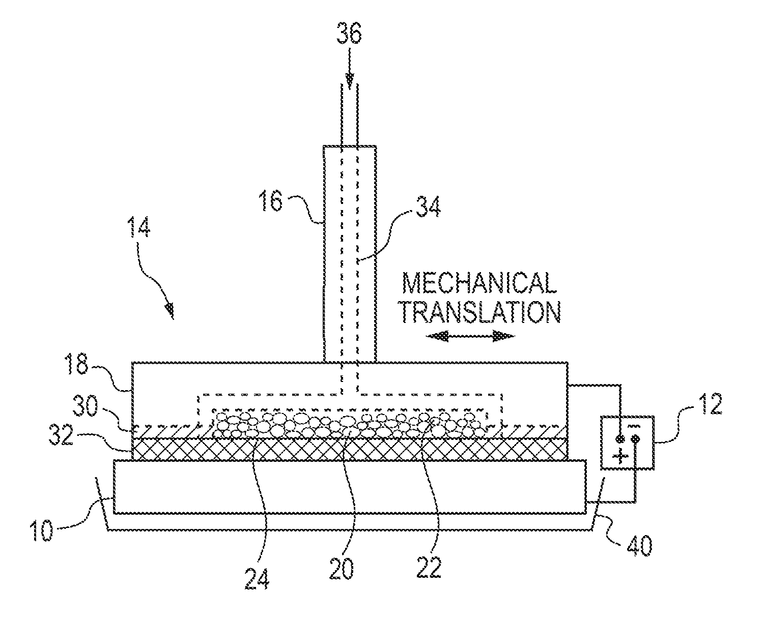
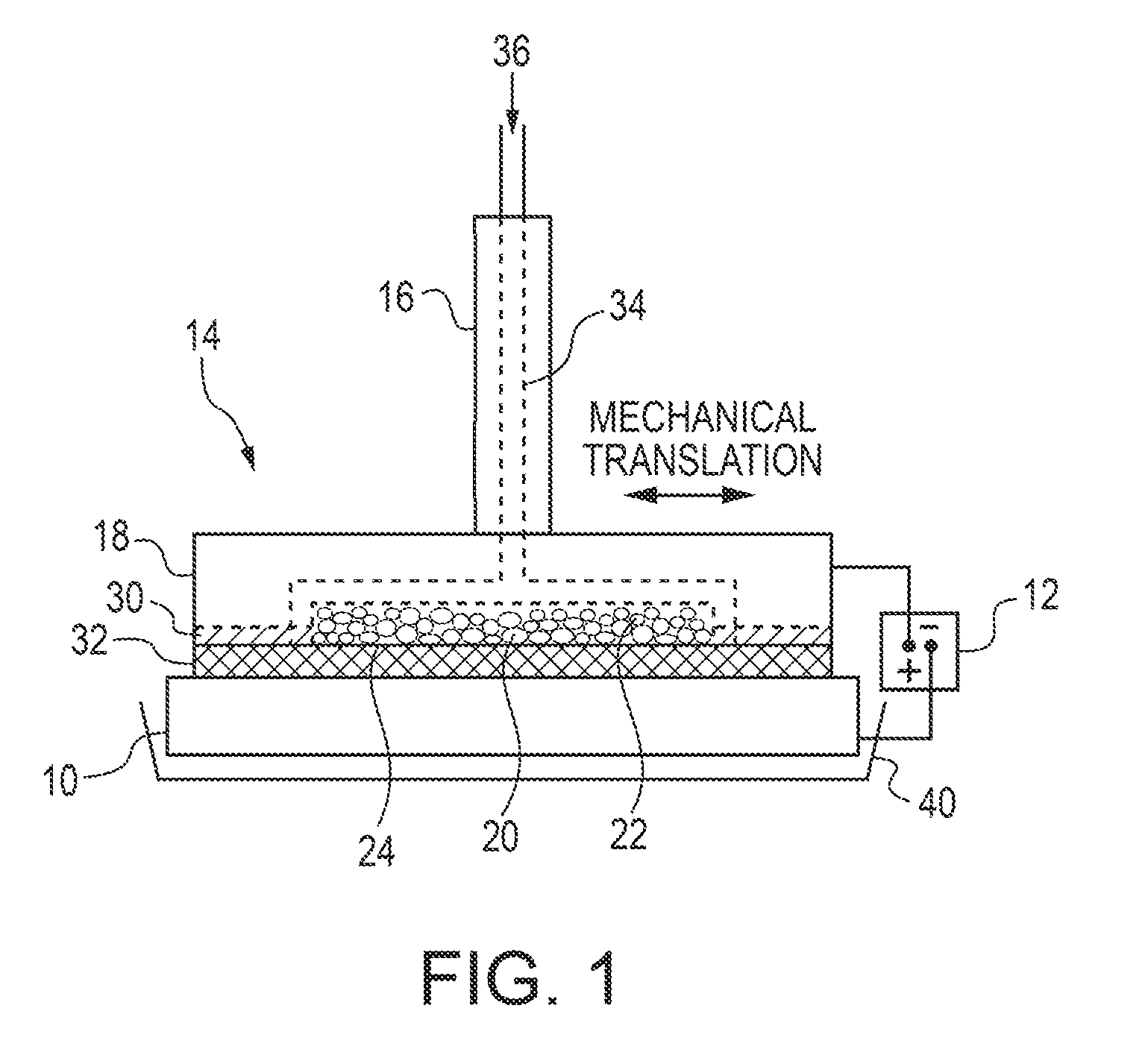
[0137]A brush plating applicator was built and operated as illustrated in FIG. 1. Specifically, a brush plating applicator (model 3030-30 Amax) from Sifco Industries Inc. (Cleveland, Ohio, USA) was suitably modified as described above. More specifically, the graphite anode applicator was modified to enable the use of DSSA or SA inserts. The brush plating applicator contained an active anode cavity having an interfacial area of up to 21 cm2 and a depth of 5 mm machined into a graphite anode tool housing which provided for electrolyte feed channels and electrical contact and served as current collector for the active anode insert. A cotton absorber was placed over the brush applicator containing the anode insert. The absorber also served as electrolyte spacer and provided a gap between the anode and cathode of ˜1 mm.

[0138]A plating solution was pumped into the modified anode brush applicator and exited through the anode inserts and the absorber...

example 2

Co Plating, Voltage with Increased Plating Time DSA, DSSA

[0144]For Example 2, the plating set up and conditions described Example 1 were used. The workpiece was a mild steel plate. The electrolyte was preheated to 80° C. The total electrolyte solution for all trials was 1.7 liters and the electrolyte was circulated at a flow rate of 300 ml / min. The anode inserts had an effective interfacial area of 21 cm2 and the current density applied was 150 mA / cm2. DSA and Co-based consumable anodes (DSSA) were employed while electrodepositing CoP as in Example 1 for 90 minutes. FIG. 4 shows the graph for the DSA and two DSSAs (one using Co on a graphite foam substrate and the other one using Co on a polymer foam substrate). FIG. 4 indicates that the applied cell voltage for DSAs was between 5 and 6V, whereas the applied cell voltage for Co-DSSA inserts on a polymer substrate was ˜1.5V. Co-DSSA inserts using Co deposited on graphite foam initially had a low applied cell voltage which, after abou...

example 3

CoP Plating, Loss of H3PO3

[0145]For Example 3, the plating set up and plating conditions described in Example 2 were used including a commercial electrolyte for depositing fine-grained Co—P alloys available from Integran Technologies Inc. (Toronto, Ontario, Canada) containing H3PO3 as the P source. The workpiece was a mild steel plate. The anode inserts had an effective interfacial area of 21 cm2 and the average current density applied was 150 mA / cm2 (300 mA / cm2 peak, 50% duty cycle) and the electrolyte was preheated to 80° C. and circulated through the anode at 300 ml / min; the resulting deposit thickness was ˜280 microns.

[0146]The H3PO3 concentration in the electrolyte was determined analytically and the drop in H3PO3 after 4.73 Ah of plating is displayed in Table 3.1. The data indicate that, with the exception of the consumable Co anode on a polymer foam carrier (average grain size 70 nm, 388 VHN), the H3PO3 loss experienced was higher than expected when the consumable Co anode u...


PUM

PropertyMeasurementUnit
thicknessaaaaaaaaaa
thicknessaaaaaaaaaa
grain sizeaaaaaaaaaa

Abstract

Anode applicators include consumable anodes, that can be operated in a non-stationary mode and are insensitive to orientation, are used in selective plating / brush electrodeposition of coatings or free-standing components. The flow-through dimensionally-stable, consumable anodes employed are perforated / porous to provide relatively unimpeded electrolyte flow and operate at low enough electrochemical potentials to provide for anodic metal / alloy dissolution avoiding undesired anodic reactions. The consumable anodes include consumable anode material(s) in high surface area to reduce the local anodic current density. During electroplating, sufficient electrolyte is pumped through the consumable anodes at sufficient flow rates to minimize concentration gradient and / or avoid the generation of chlorine and / or oxygen gas and / or undesired reaction such as the anodic oxidation of P-bearing ions in the electrolyte. The active consumable anode material(s) can have a microstructure which is fine-grained and / or amorphous to ensure a uniform anodic dissolution.

Description

FIELD OF THE INVENTION[0001]Exemplary embodiments herein relate to the selective plating / brush plating of coatings or free-standing components employing non-stationary, consumable anodes. The inventive anode inserts are perforated / porous to provide relatively unimpeded electrolyte flow and comprise the consumable anode material in high surface area to reduce the effective local anodic current density. During electroplating, sufficient electrolyte is pumped through the consumable anodes at sufficient flow rates to minimize or avoid the generation of chlorine and / or oxygen gas and / or undesired reaction such as the anodic oxidation of phosphorus-bearing ions in the electrolyte. According to one embodiment, the consumable anode material has a microstructure which is fine-grained and / or amorphous.BACKGROUND OF THE INVENTION[0002]Electrodeposited metallic coatings applied by selective and / or brush plating are extensively used in consumer and industrial applications. In brush plating, dime...

Claims


Application Information

Patent Timeline
Patent Type & Authority Applications(United States)
IPC IPC(8): C25D17/10C25D21/18
CPCC25D5/06C25D17/14C25D1/00C25D5/08C25D5/18C25D5/617C25D5/619C25D5/67
Inventor TOMANTSCHGER, KLAUSFACCHINI, DIANAGONZALEZ, FRANCISCOMCCREA, JONATHANKRATOCHWIL, JOHNWOLOSHYN, DANBISMILLA, YUSUFNAGARAJAN, NANDAKUMARNEACSU, MIOARA
Owner INTEGRAN TECH
Why Eureka
Try Eureka