Hydraulic design method for asymmetric solid-liquid two-phase flow centrifugal impeller

A centrifugal impeller, hydraulic design technology, applied in mechanical equipment, non-variable-capacity pumps, liquid fuel engines, etc., can solve the problems of poor non-destructiveness, reduced production efficiency, changes in slurry performance, etc., and achieves improved streamline distribution. The effect of improving clogging and entanglement resistance

Active Publication Date: 2016-01-06
JIANGSU UNIV
View PDF10 Cites 6 Cited by
  • Summary
  • Abstract
  • Description
  • Claims
  • Application Information

AI Technical Summary

Problems solved by technology

But it has the following defects: (1) poor non-destructiveness, great damage to the transported materials, and easy to change the performance of the slurry; (2) not suitable for transporting the slurry containing long fiber materials; (3) the flow-lift performance curve is relatively Flat; (4) Due to the existence of circulating flow, the hydraulic loss is large and the efficiency of the pump is low
[0005] After retrieval, the patents related to the present invention include: a design method for the impeller of a single-channel cutting pump (publication number: CN102410245A), an impeller design method for a single-channel cutting pump was invented, and the main geometric parameters of the blades are given Design formulas for outer diameter, outlet width, and inlet diameter, but the inlet and outlet placement angles of the blades are not given; a solid-liquid two-phase flow screw centrifugal pump (CN102400919A) invented a screw centrifugal pump with a sleeve at the inlet section of the pump, and a sleeve The fixed guide vane of the cylinder, the joint action of the guide vane and the spiral blade effectively prevents the accumulation of fibrous solid matter in the pump, enhances the passability of the pump, and improves the delivery performance of the screw centrifugal pump for solid matter and liquid. When pulping, due to the existence of fixed guide vanes, the pulp cannot be gathered together, which reduces the production efficiency

Method used


Image

  • Hydraulic design method for asymmetric solid-liquid two-phase flow centrifugal impeller
  • Hydraulic design method for asymmetric solid-liquid two-phase flow centrifugal impeller
  • Hydraulic design method for asymmetric solid-liquid two-phase flow centrifugal impeller

Examples


Embodiment Construction

[0087] Design requirements: the flow rate under design conditions is 0.096764 cubic meters per second, the head under design conditions is 60 meters, the speed is 2950 revolutions per second, and g is 10 meters per square meter.

[0088] (1)

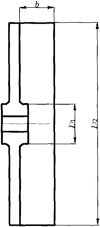
[0089] (2) Impeller inlet diameter:

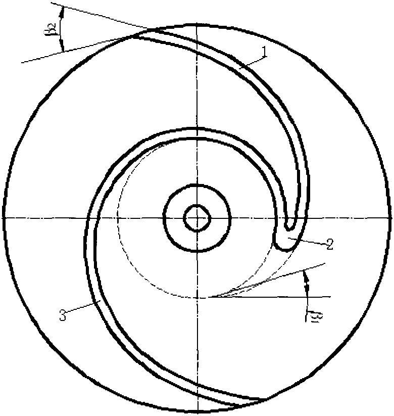
[0090] (3) Blade inlet installation angle:

[0091] (4) Blade outlet installation angle:

[0092] (5) Impeller outlet diameter

[0093] (6) Blade width:

[0094] (7) Streamline equation of working face with long blades:

[0095] (8) The streamline equation of the short blade face:

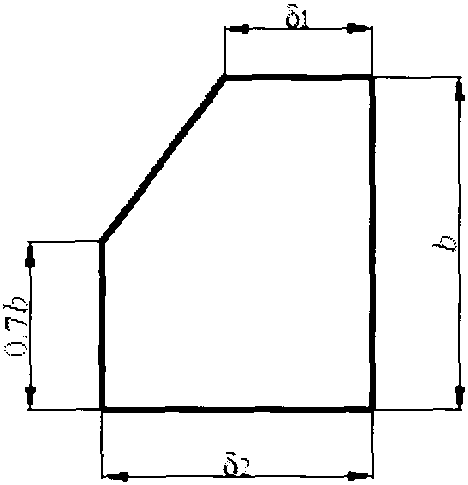
[0096] (9) The polar equation of the size and fillet of the impeller:

[0097] (10) Blade bottom thickness: δ 2 =0.00012n s +0.003955=0.00012×100+0.0039≈0.016

[0098] In the design process, the selection of other coefficients needs to be selected according to the actual situation. For example, the shape of the blade inlet needs to be selected according to the shape of the inlet suction chamber ...


PUM


Abstract

The invention provides a hydraulic design method for an asymmetric solid-liquid two-phase flow centrifugal impeller. The method aims at solving the problems generated in the application process of a solid-liquid two-phase flow pump. An impeller is a semi-open type single flow channel and is suitable for conveying various particles and substances containing fibers. A vane is formed by combining a long vane body and a short vane body. Part of the short vane body and part of the long vane body are symmetric. The flow guide effect is achieved through the long vane body so that the conveyed substances can smoothly reach an impeller outlet and the integrity of the conveyed substances cannot be damaged. The conveyed substances are discharged out of the impeller under the effect of the short vane body. A working face streamline equation of the vane is designed through an arc method and a variable angle spiral line method jointly. In order to rotationally cut various objects, the vane is designed in the manner that the working face is higher than the back face, and the cross section of the vane is designed in a pentagonal shape with three right angles. Inlet and outlet installation angle design formulas of the vane are given. The asymmetric solid-liquid two-phase flow centrifugal impeller designed through the method is good in blockage resistance and high in twining cutting resistance.

Description

technical field [0001] The invention relates to a hydraulic design method of a centrifugal pump, in particular to a hydraulic design method of a centrifugal impeller for conveying asymmetric solid-liquid two-phase flow. Background technique [0002] With the continuous development of industrial and agricultural production, in mining, chemical industry, food, water power. papermaking. In the discharge of industrial processes, domestic sewage and industrial wastewater in many industries such as metallurgy and construction, it is necessary to transport two-phase flows of different solid particles, particle sizes, volume concentrations, and hardness. Solid-liquid two-phase flow centrifugal pumps are widely used. [0003] At present, the impeller structures of solid-liquid two-phase flow centrifugal pumps are mainly single and double channel impellers, swirl impellers, etc. Due to the special impeller structure of the large channel, the single-channel impeller has good non-dest...

Claims


Application Information

Patent Timeline
Patent Type & Authority Applications(China)
IPC IPC(8): F04D29/22
Inventor 王秀礼钟华舟朱荣生付强
Owner JIANGSU UNIV
Why Eureka
Try Eureka