Bipitch chain transmission mechanism

A chain drive, double-pitch technology, applied in the direction of transmission chain, transmission device, mechanical equipment, etc., can solve the problems of fast wear, affecting the working reliability and service life of the bucket chain elevator, and easy blockage of the meshing area of ​​the chain teeth. , to achieve the effect of improving reliability, less chain assembly parts, and uniform force

Active Publication Date: 2016-01-06
ANHUI UNIVERSITY OF TECHNOLOGY
View PDF8 Cites 7 Cited by
  • Summary
  • Abstract
  • Description
  • Claims
  • Application Information

AI Technical Summary

Problems solved by technology

[0005] The main purpose of the present invention is to provide a chain transmission mechanism suitable for bucket chain elevators, which overcomes the problems that the meshing area of ​​the chain teeth is easily blocked and wears quickly in general chain transmissions, which affects the working reliability and service life of bucket chain elevators.

Method used


Image

  • Bipitch chain transmission mechanism
  • Bipitch chain transmission mechanism
  • Bipitch chain transmission mechanism

Examples


Embodiment Construction

[0021] The present invention will be further described below in conjunction with the accompanying drawings and specific embodiments.

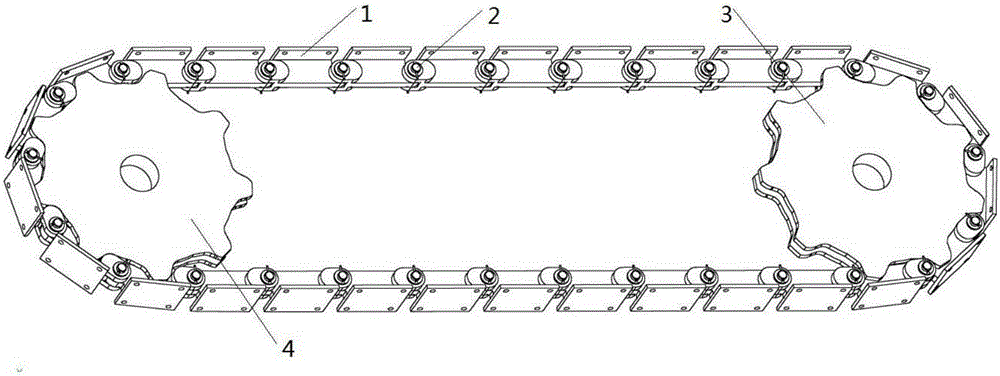
[0022] figure 1 The middle driving sprocket 3 is located at the driving end, and the driven sprocket 4 is located at the driven end, their axes are parallel, the structures are identical and they are located in the same motion plane. When the driving sprocket 3 rotates clockwise, the contact between the driving sprocket 3 and the chain link 1 is located in the primary meshing area; and the contact between the driven sprocket 4 and the chain link 1 is located in the secondary meshing area. When the driving sprocket 3 rotates counterclockwise, there will be a certain relative sliding between the teeth of the sprocket and the chain link 1, which is convenient for removing the blocking material in the meshing area and preventing the transmission mechanism from being stuck or unable to start.

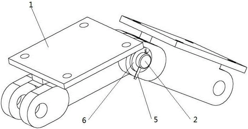
[0023] figure 2 is a schematic diagram of the assemb...


PUM


Abstract

The invention discloses a bipitch chain transmission mechanism, and belongs to the technical field of material digging and conveying equipment. The bipitch chain transmission mechanism comprises a series of integral chain links, pin shafts, a driving chain wheel and a driven chain wheel. The front chain links and the rear chain links are completely the same in structure and are connected to form a closed transmission chain through the same pin shafts. The driving chain wheel and the driven chain wheel are the same in structure, and the axis of the driving chain wheel is parallel to that of the driven chain wheel. The pitch that the driving chain wheel and the transmission chain are engaged serves as the main pitch, the pitch that the driven chain wheel and the transmission chain are engaged serves as the auxiliary pitch, and the main pitch is larger than the auxiliary pitch. The chain transmission mechanism is suitable for bucket chain type lifers in severe work environments, and has the beneficial effects of being high in work reliability, long in service life, large in bearing capacity and the like.

Description

technical field [0001] The invention belongs to the technical field of material excavation and conveying equipment, and in particular relates to a double-pitch chain transmission mechanism. Background technique [0002] Bucket chain elevator is a kind of mechanical equipment used for underwater excavation of sandstone, steel slag, and silt. The excavation hopper is fixed on the chain link, the driving sprocket is located above, and the driven sprocket is located below (usually underwater ), the mining hopper is driven by the driving sprocket to complete the tasks of digging, conveying and unloading. Due to the harsh working environment of the chain transmission mechanism of the bucket chain elevator, especially in the steel slag treatment of wind quenching, wind crushing and water quenching, the water temperature is high, the alkalinity is large, the slag grains have a large difference in thickness and high hardness, the traditional sleeve The roller chain has many sliding ...

Claims


Application Information

Patent Timeline
Patent Type & Authority Applications(China)
IPC IPC(8): F16H7/06F16G13/06
CPCF16G13/06F16H7/06
Inventor 张玉华李彪
Owner ANHUI UNIVERSITY OF TECHNOLOGY
Why Eureka
Try Eureka