Parallel type mutual-assistance defrosting air source heat pump water heater

An air source heat pump, parallel technology, applied in fluid heaters, lighting and heating equipment, damage protection and other directions, can solve the problems of inability to carry out, low efficiency of heat pump water heaters, high cost, etc., to achieve the effect of ensuring mutual assistance of heat

Inactive Publication Date: 2016-01-06
ZHEJIANG WANBAO NEW ENERGY TECH
View PDF6 Cites 5 Cited by
  • Summary
  • Abstract
  • Description
  • Claims
  • Application Information

AI Technical Summary

Problems solved by technology

However, when the air source heat pump is used in humid weather where the temperature is close to zero in winter, it is easy to frost, the defrosting is not complete, and the efficiency is low
Since the direct-heating air source heat pump water heater can directly and continuously output hot water at the set temperature no matter how low the water temperature is, it can be heated by the heat pump water heater, and the quality of the hot water is stable. Compared with the water storage tank circulation heating method, there are many advantages; because the water storage tank circulation heating method needs to run for a long time before the heat pump water heater can get hot water, and when the water temperature of the water tank is close to the set high temperature, the efficiency of the heat pump water...

Method used


Image

  • Parallel type mutual-assistance defrosting air source heat pump water heater
  • Parallel type mutual-assistance defrosting air source heat pump water heater
  • Parallel type mutual-assistance defrosting air source heat pump water heater

Examples


Embodiment 1

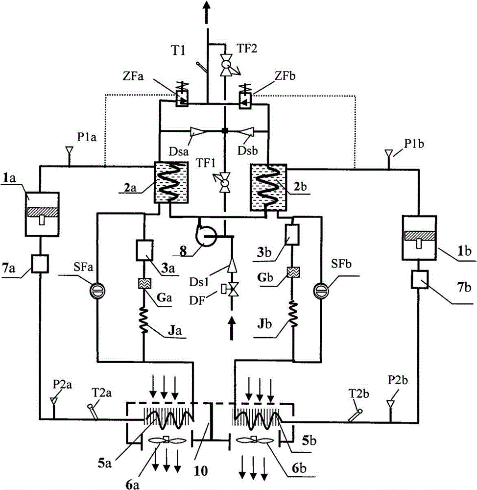
[0033] The structural relation and working principle of embodiment 1 are by figure 1 and Figure 6 illustrate.

[0034] figure 1 As shown, it is a schematic diagram of the structural relationship between the refrigerant circuit system and the hot water heat exchange system of a parallel mutual defrosting air source heat pump water heater using bypass hot gas defrosting in Embodiment 1 of the present invention; The mutual defrosting air source heat pump water heater includes two independent refrigerant circuit systems, a parallel hot water internal circulation hot water heat exchange system, and a unified signal acquisition and circuit control system; figure 1 As shown, the two refrigerant circuit systems are respectively system a and system b, and the accessories of the two systems are represented by footnotes a and b respectively; taking system a as an example, the composition and connection mode of the refrigerant circuit system are described: a system consists of compres...

Embodiment 2

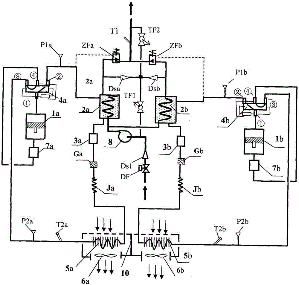
[0039] The structural relation and working principle of embodiment 2 are by figure 2 illustrate.

[0040] Such as figure 2 As shown, a parallel mutual defrosting air source heat pump water heater using reverse cycle defrosting in Embodiment 2 of the present invention includes two independent refrigerant circuit systems, system a and system b, and the accessories of the two systems are Indicated by footnotes a and b; a parallel hot water heat exchange system with internal circulation of hot water, a unified signal acquisition and circuit control system; taking system a as an example, explain the composition and connection mode of the refrigerant circuit system: It also includes a four-way valve 4a; note, the single interface on one side of the main valve body of the four-way valve is the first interface ① of the four-way valve, and the three interfaces on the other side of the main valve body of the four-way valve are agreed in the four-way valve The interface connected to ...

Embodiment 3

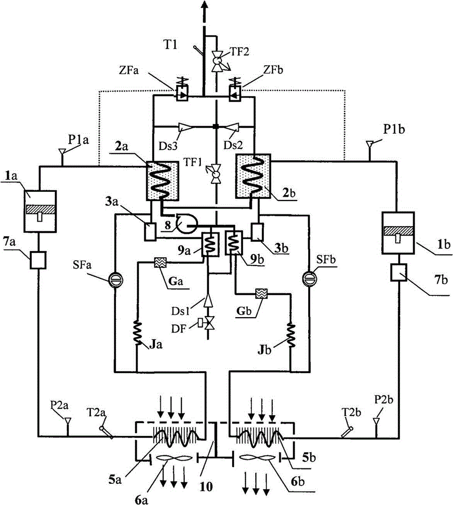
[0044] The structural relationship and working principle of the parallel mutual defrosting air source heat pump water heater of embodiment 3 are given by image 3 illustrate.

[0045] image 3 Shown is the composition and working principle diagram of a parallel mutual defrosting air source heat pump water heater with bypass hot gas defrosting and subcooler in embodiment 3. There are two independent refrigerant circuit systems a system and b system, a parallel hot water heat exchange system with internal circulation of hot water, a unified signal acquisition and circuit control system.

[0046] image 3 The parallel mutual defrosting air source heat pump water heater and the shown embodiment 3 figure 1 The difference between the shown parallel air source heat pump water heaters with mutual defrosting is that subcoolers 9a and 9b are respectively added between the outlet of the liquid receiver and the inlet of the restrictor of the two refrigerant loop systems, and the filter...


PUM


Abstract

The invention discloses a technical scheme of a parallel type mutual-assistance defrosting air source heat pump water heater. The parallel type mutual-assistance defrosting air source heat pump water heater is characterized in that a unit is provided with two or more refrigerant loop systems, and defrosting is sequentially performed in two groups. Air inlet ducts of the two systems are isolated through a partition plate. Water inlets of hot water heat exchangers of the systems are connected with a water outlet of a circulating water pump in parallel. Water outlets of the hot water heat exchangers are each divided into two paths of connectors; after being connected with a constant temperature water outflow valve, one path of connector is connected to a hot water outflow main pipe in parallel, and after being connected with a check valve, the other path of connector is connected to a circulating water main pipe in parallel; the circulating water main pipe provided with a circulating water regulating valve and a water inflow pipe are connected to a water inlet of the circulating water pump together in parallel, and a parallel type hot water heat exchange system for hot water inner circulation is formed; during defrosting, the defrosting system is switched to bypass hot gas or reverse circulating dedusting, the other system continues to perform heating circulation, the two systems perform defrosting in a mutual-assistance manner through hot water inner circulation, the defrosting problem of the air source heat pump water heater is thoroughly solved, and the worry that defrosting is not thorough is avoided forever; and in addition, due to the addition of the system of a supercooler, efficiency can be improved by 15%.

Description

technical field [0001] The invention relates to the technical field of heat pump water heaters. Background technique [0002] The air source heat pump water heater absorbs heat from the air, and supplies hot water for domestic use after raising the temperature. The energy efficiency ratio is in the range of 2.5 to 4. Therefore, it is a good product for energy saving. However, when the air source heat pump is used in humid weather where the temperature is close to zero in winter, it is easy to frost, the defrosting is not complete, and the efficiency is low. Since the direct-heating air source heat pump water heater can directly and continuously output hot water at the set temperature no matter how low the water temperature is, after being heated by the heat pump water heater, the quality of the hot water is stable, and hot water can be obtained when the heat pump water heater is started Compared with the water storage tank circulation heating method, there are many advanta...

Claims


Application Information

Patent Timeline
IPC IPC(8): F24H4/02F25B47/02
Inventor 巨小平
Owner ZHEJIANG WANBAO NEW ENERGY TECH
Why Eureka
Try Eureka