Feed dryer

A dryer and feed technology, applied in the direction of progressive dryer, drying of solid materials, drying, etc., can solve the problems of long drying time and low heat transfer efficiency, so as to improve the effect, improve the efficiency of heating, and improve the efficiency of heating. effect of effect

Inactive Publication Date: 2016-01-06
CHONGQING UNION MACHINE MFG
View PDF1 Cites 4 Cited by
  • Summary
  • Abstract
  • Description
  • Claims
  • Application Information

AI Technical Summary

Problems solved by technology

[0005] The present invention intends to provide a feed dryer to solve the problem of low heat transfer efficiency and long drying time in the prior art due to no direct contact between the material and the heat source

Method used


Image

  • Feed dryer

Examples


Embodiment 1

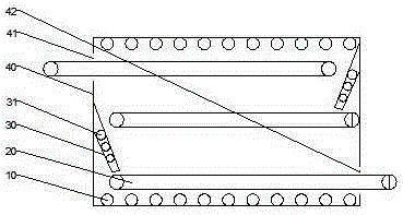
[0016] like figure 1 As shown, the scheme of the feed dryer is as follows: it includes a box body 40 and a horizontally arranged conveyor belt 20 , the upper part of the box body 40 is provided with a feed port 41 , and the lower part of the box body 40 is provided with a discharge port 42 . The conveyor belt 20 is located inside the box body 40 . The conveyor belt 20 is multi-layered and arranged in parallel. One end of the uppermost conveyor belt stretches out of the feed port 41 , and one end of the bottom conveyor belt stretches out of the discharge port 42 . A baffle 30 is arranged between the output end of the conveyor belt and the input end of the lower conveyor belt. The baffle 30 is obliquely arranged on the box body 40. A heating pipe 31 is arranged in the baffle plate 30. The top surface and the bottom surface of the inner wall of the box body 40 A heat pipe 10 is provided.

[0017] In addition, in this embodiment, the conveyor belt 20 has at least three layers. T...


PUM

PropertyMeasurementUnit
Angleaaaaaaaaaa

Abstract

The invention discloses a feed dryer. According to the scheme, the feed dryer comprises a box body and horizontal conveyor belts, wherein a feeding hole is formed in the upper part of the box body; a discharge hole is formed in the lower part of the box body; a plurality of layers of parallel conveyor belts are positioned inside the box body; one end of the uppermost layer of conveyor belt extends into the feeding hole; one end of the bottommost layer of conveyor belt extends out of the discharge hole; baffle plates are arranged between the discharge ends of the conveyor belts and the feeding ends of the lower layers of conveyor belts; the baffle plates are arranged on the box body in an inclined mode; heating tubes are arranged in the baffle plates; and heat tubes are arranged on the top surface and the bottom surface of the inner wall of the box body. The invention aims to provide the feed dryer which solves the problems of low heat transmission efficiency and longer drying time due to the fact that materials are not in direct contact with a heat source in the prior art.

Description

technical field [0001] The invention relates to a feed dryer. Background technique [0002] Existing equipment for drying powder, granular, and flake materials in chemical industry, food feed, agricultural and sideline product processing and other fields are mainly drum dryers, airflow dryers and fluidized bed dryers. The heat transfer coefficient of the device is small, the thermal efficiency is low, the airflow dryer and the fluidized bed dryer have poor adaptability to the material, the airflow dryer is generally only used for drying powder materials with relatively uniform particles, and the fluidized bed dryer is mainly used For the drying of granular or flake materials, it has higher requirements on the particle distribution of the material, and sometimes there will be channeling or surging during the drying process, which will cause the heat transfer coefficient to drop sharply. [0003] In order to solve the above problems, the patent document with the publication n...

Claims


Application Information

Patent Timeline
IPC IPC(8): F26B15/12F26B23/00F26B25/00
Inventor 邓雪峰
Owner CHONGQING UNION MACHINE MFG
Why Eureka
Try Eureka