Electromagnetic immunity testing system building method

An electromagnetic immunity and testing system technology, applied in the direction of measuring electricity, measuring devices, measuring electrical variables, etc., can solve problems affecting equipment sampling, feedback, triggering, being susceptible to electromagnetic interference, and reducing equipment technical performance indicators, etc. The effect of improving the service life and environmental adaptability, improving the actual reference value, and reducing the space occupied

Inactive Publication Date: 2016-01-06
LASER FUSION RES CENT CHINA ACAD OF ENG PHYSICS
View PDF5 Cites 7 Cited by
  • Summary
  • Abstract
  • Description
  • Claims
  • Application Information

AI Technical Summary

Problems solved by technology

Electrical equipment works in the case of transient strong discharge, and is susceptible to electromagnetic interference during operation. In particular, during the pulse generation process, it will receive serious electromagnetic interference, which will affect the sampling, feedback, triggering and other signal control operations of the equipment, reducing Equipment technical performance indicators

Method used


Image

  • Electromagnetic immunity testing system building method
  • Electromagnetic immunity testing system building method
  • Electromagnetic immunity testing system building method

Examples


Embodiment 1

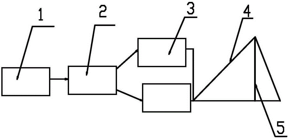
[0046] Such as Figure 1-2 As shown, the test system includes a measurement system 1, a control system 2, a pulsed high voltage source 3 and a bounded waveguide transmission line 4 connected in sequence, and there are two pulsed high voltage sources 3.

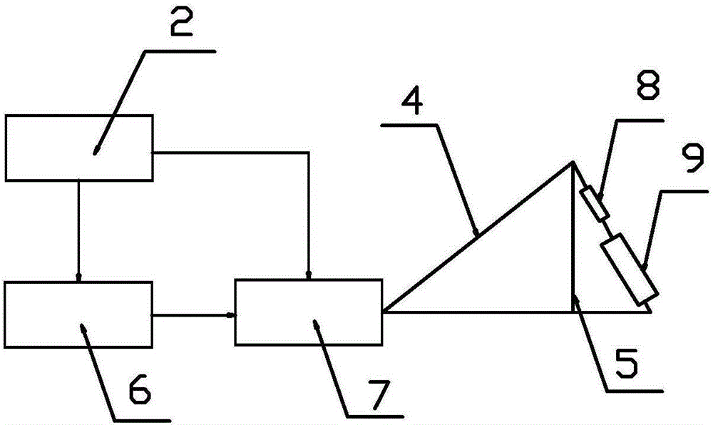
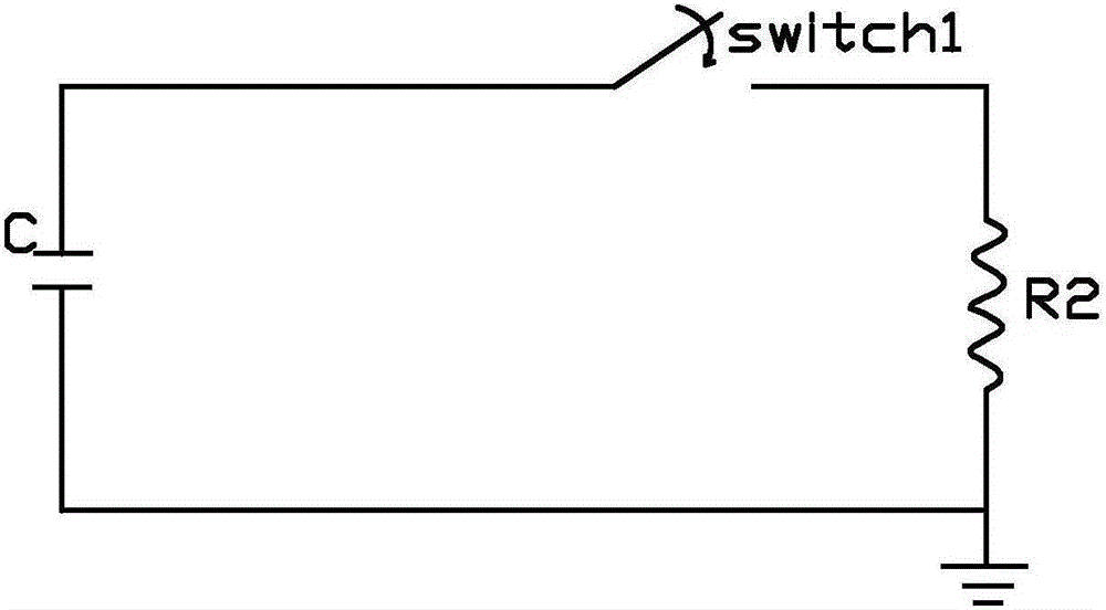
[0047] The pulsed high-voltage source 3 outputs a voltage with adjustable amplitude, which can adapt to the requirements of electromagnetic field amplitude changes, can flexibly configure various experimental environments, and has strong practicability. The pulsed high-voltage source 3 includes a high-voltage DC charging power supply 6, a Marx generator 7. The Marx generator 7 includes an outer casing, a capacitor C m , gas gap switch and discharge resistor R 2 , the discharge resistor R 2 with snubber resistor R 1 equal.

[0048] The control system 1 mainly has two functions of electrical control and air circuit control. The electrical control acts on the high-voltage DC charging power supply 6 to realize closing, voltage...

Embodiment 2

[0073] According to the establishment method of a kind of electromagnetic immunity test system described in Embodiment 1, simulate the transient strong discharge environment of the Shenguang-III host device, select a laboratory of 9m*6m*3.6m, according to the test equipment to be tested The maximum size, determine the radiation field test area as 0.5m*0.5m*0.5m.

[0074] The electromagnetic pulse radiation field of the Shenguang-III host device has two types:

[0075] (1) The discharge voltage is 20,000 volts, T r for 1 µs, T h 600 microseconds, the output pulse electric field amplitude is 100V / m~1000V / m, and the pulse voltage amplitude is 200V~15KV;

[0076] (2) The discharge voltage is 20,000 volts, T r less than 20 ns, T h 200 nanoseconds, the amplitude of the output pulse electric field is 1000V / m-8000V / m, and the amplitude of the pulse voltage is 200V-15KV.

[0077] The bounded waveguide transmission line 4 is set as a wire grid tapered and distributed structure, whi...


PUM


Abstract

The invention discloses an electromagnetic immunity testing system building method, which comprises a measurement system, a control system, two pulse high voltage sources and a bounded waveguide transmission line connected in sequence. The testing system building method comprises steps: 1, according to long pulse and short pulse in a theoretical electromagnetic pulse radiation field, technical parameters of a transient electromagnetic field are determined respectively; 2, according to the technical parameters, parameter setting on the bounded waveguide transmission line and the two pulse high voltage sources is carried out; 3, the two pulse high voltage sources are respectively connected with the bounded waveguide transmission line; and 4, whether deviation of technical parameters of an actual electromagnetic pulse radiation field meets design standards is verified. The service life and the environmental adaptability of a tested device can be improved, the cost is saved, the design accuracy is high, the actual system parameter reference value is large, various experimental environments can be configured flexibly, and practicability is strong.

Description

technical field [0001] The invention relates to the technical field of laser equipment, in particular to a method for establishing an electromagnetic immunity test system. Background technique [0002] The interaction of electric field and magnetic field produces electromagnetic waves, and the phenomenon that electromagnetic waves are emitted or leaked into the air is called electromagnetic radiation. Electromagnetic radiation is an invisible and intangible substance that exists in a special form. Electrical equipment works in the case of transient strong discharge, and is susceptible to electromagnetic interference during operation. In particular, during the pulse generation process, it will be subject to serious electromagnetic interference, which will affect the sampling, feedback, triggering and other signal control operations of the equipment, reducing the The technical performance index of the equipment. [0003] "Electromagnetic pollution" has become the fifth large...

Claims


Application Information

Patent Timeline
Patent Type & Authority Applications(China)
IPC IPC(8): G01R31/00
Inventor 汪凌芳党钊唐菱黄建军陈骥王超李克洪
Owner LASER FUSION RES CENT CHINA ACAD OF ENG PHYSICS
Why Eureka
Try Eureka