Head-mounted virtual reality apparatus and control method therefor based on mobile terminal

A mobile terminal and virtual reality technology, applied in the field of virtual reality, can solve problems such as complex operation, immature technology, and high price, and achieve the effects of simple operation, novel effect, and low manufacturing cost

Active Publication Date: 2016-01-06
厦门九品芝麻信息科技有限公司
View PDF4 Cites 4 Cited by
  • Summary
  • Abstract
  • Description
  • Claims
  • Application Information

AI Technical Summary

Problems solved by technology

[0003] However, due to the fact that this technology has not long entered the public eye, the technology is not very mature. Some products on the market are relatively expensive and complicated to operate, and there is still a long way to go before it can be truly popularized.

Method used


Image

  • Head-mounted virtual reality apparatus and control method therefor based on mobile terminal
  • Head-mounted virtual reality apparatus and control method therefor based on mobile terminal
  • Head-mounted virtual reality apparatus and control method therefor based on mobile terminal

Examples


Embodiment 1

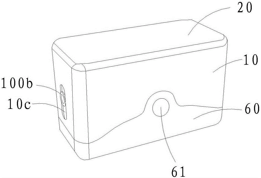
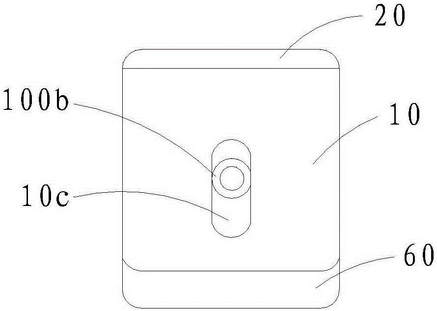
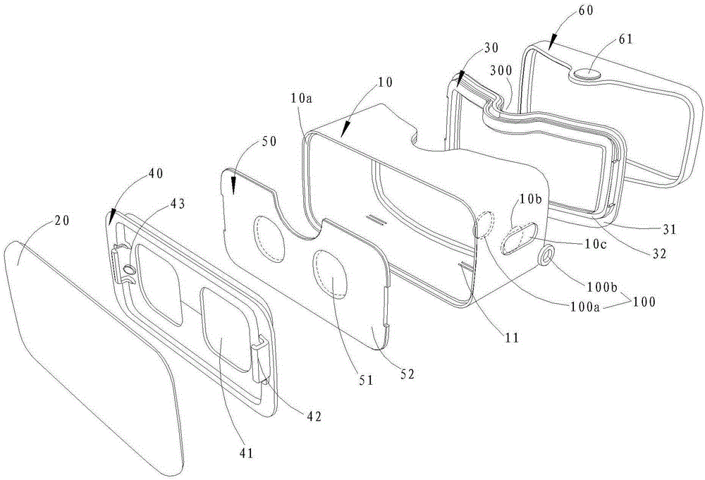
[0032] See Figure 1 ~ Figure 3 , The head-mounted virtual reality device of the present invention is used in conjunction with mobile terminals (such as smart phones, tablet computers, etc.), and includes a box body 10, a front cover 20, an observation cover 30, a terminal placement plate 40, a lens assembly 50, and a rear The cover 60 and the trigger module (the trigger module of this embodiment is the detection magnet 43 fixed on the terminal placement plate 40), the box body 10 is a cylindrical structure with open front and rear ends, and the terminal placement plate 40 and the lens assembly 50 are from front to back (Such as image 3 (Shown direction) are arranged in the box body 10 sequentially. The lens assembly 50 is composed of a lens 51 and a lens holder 52. The lens holder 52 is provided with two adjacent lens mounting holes (not marked); the front cover 20 is locked by It is detachably covered on the front opening of the box body 10 in a similar manner, the observati...

Embodiment 2

[0049] Such as Figure 7 As shown, the difference from Embodiment 1 is that the trigger module of this embodiment is a pressure sensor 44 fixed on the terminal placement plate 40. Preferably, the pressure sensor 44 is fixed on the middle of the terminal placement plate 40 and is located at two transparent Between holes 41. After the mobile terminal is completely snapped and placed between the two buckles 42 and attached to the terminal placement plate 40, the pressure sensor 44 contacts the mobile terminal to generate a trigger signal to start the corresponding background program or APP.

Embodiment 3

[0051] Such as Figure 8 As shown, the difference from Embodiment 1 is that the trigger module of this embodiment is an infrared sensor 53 fixed on the lens holder 52. The infrared sensor 53 emits light through the light-transmitting hole 41 to detect whether there is a mobile terminal on the terminal placement board 40. In other embodiments, the infrared sensor 53 may also be fixed on the front cover 20 or located on the inner wall of the box body 10 between the terminal placement plate 40 and the lens assembly 50.


PUM


Abstract

The invention discloses a head-mounted virtual reality apparatus based on a mobile terminal. The apparatus comprises a box body provided with openings at a front end and a rear end, an observing mask covered on the rear-end opening of the box body, a terminal placing plate, and a lens assembly comprising a lens that are disposed in the box body successively from the front end to the rear end, and a magnetic adjusting assembly. A light transmitting hole corresponding to the lens is drilled on the terminal placing plate. The magnetic adjusting assembly is fixed to a sidewall of the box body and is used for generating a variable magnetic field. The present invention also discloses a control method of the head-mounted virtual reality apparatus based on the mobile terminal. The head-mounted virtual reality apparatus provided by the present invention has the advantages of a simple structure, low manufacturing costs, and relatively high practicability. A user can simply place the mobile terminal on the terminal placing plate to obtain an immersive experience with a vivid image and novel effects via the mobile terminal, thereby greatly reducing the threshold of using the virtual reality apparatus and having high popularization. Meanwhile, the user can control the mobile terminal without the need of removing the mobile terminal from the head-mounted virtual reality apparatus, so that operations are more simple.

Description

Technical field [0001] The present invention relates to the field of virtual reality technology, in particular to a head-mounted virtual reality device based on a mobile terminal and a control method thereof. Background technique [0002] With the popularization of intelligent hardware, virtual reality technology gradually enters people’s field of vision and is familiar to the public. It is a computer simulation system that can create and experience virtual worlds. It combines simulation technology with computer graphics, human-machine interface technology, and multimedia. Technology, sensor technology, network communication technology and other technologies are combined together, through interactive three-dimensional dynamic vision and physical behavior system simulation to immerse users in the environment, and use the helmet display to seal the user’s vision and hearing. , To produce virtual vision, and some can also use data gloves to close the user’s hand feeling channel to p...

Claims


Application Information

Patent Timeline
Patent Type & Authority Applications(China)
IPC IPC(8): G06F3/01
Inventor 黄弘毅郭丁嘉李文铨
Owner 厦门九品芝麻信息科技有限公司
Why Eureka
Try Eureka