Supercharge Your Innovation With Domain-Expert AI Agents!

Control system of 3D printer

A 3D printer and control system technology, applied in the direction of digital output to printing unit, energy-saving calculation, climate sustainability, etc., can solve the problems of affecting printing effect, unfavorable heat dissipation of devices, high cost, etc., to achieve human-computer interaction function, reduce The cost of board making and the effect of simple structure

Inactive Publication Date: 2016-01-06
MICOLOR DIGITAL TECH CO LTD
View PDF5 Cites 11 Cited by
  • Summary
  • Abstract
  • Description
  • Claims
  • Application Information

AI Technical Summary

Problems solved by technology

The control component controls the temperature of the nozzle. When the temperature of the nozzle cannot be kept constant during the printing process, it will affect the filament extrusion effect of the consumables. When it is too low, it will affect the adhesion effect of the model on the printing platform; the control component controls the movement of each positioning axis, when the movement is not tightly connected, the positioning is not accurate, it will easily cause motion shock, over-processing of the model, etc.; the control component controls the extrusion of the extruder , when the extrusion length is inaccurately controlled, it is easy to cause insufficient or too much consumables for the printed model, which will affect the printing effect
The control function of the control component is mainly realized by the control system. The circuit structure of the existing dual-nozzle 3D printer control system is relatively complicated. Usually, multiple DSPs or multiple FPGAs plus ARM are used as the core controller, plus various functional peripherals The entire control system is composed, which leads to the control system being too complex. The control system is too complex, which not only increases the power consumption of the device, but also is not conducive to the heat dissipation of the device, which affects the function and life of the controller, and also makes the cost higher.

Method used


Image

  • Control system of 3D printer
  • Control system of 3D printer
  • Control system of 3D printer

Examples


Embodiment Construction

[0041] The present invention will be further described in detail below in conjunction with the embodiments and the accompanying drawings.

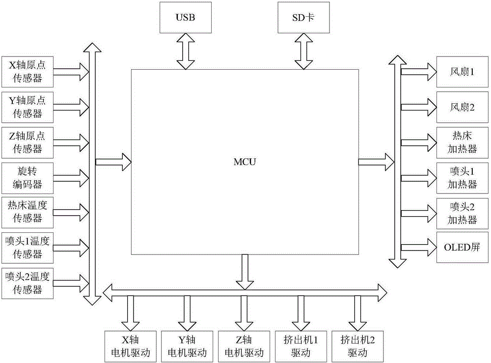
[0042] figure 1 Shown is the hardware block diagram of the 3D printer control system of the present invention, including the micro control unit MCU, the micro control unit MCU is respectively connected with USB interface, SD card interface, X-axis origin sensor, Y-axis origin sensor, Z-axis origin sensor, rotary encoder Sensor, hot bed temperature sensor, nozzle 1 temperature sensor (namely the first nozzle temperature sensor), nozzle 2 temperature sensor (namely the second nozzle temperature sensor), X-axis motor drive, Y-axis motor drive, Z-axis motor drive, extrusion Machine 1 drive (that is, the first extruder drive), extruder 2 drive (that is, the second extruder drive), fan 1 (that is, the first fan), fan 2 (that is, the second fan), hot bed heater , Extruder 1 heater (namely the first extruder heater), extruder 2 heater (i.e. the s...


PUM


Abstract

The invention puts forward a control system of a 3D printer, which comprises a micro-control unit MCU used to control interactions between printing equipment and externally connected equipment, wherein the micro-control unit MCU is respectively connected to a USB interface, an SD card interface, an X-axis origin sensor, a Y-axis origin sensor, a Z-axis origin sensor, a rotary encoder, a hot bed temperature sensor, a sprayer temperature sensor, an X-axis motor drive, a Y-axis motor drive, a Z-axis motor drive, an extruder drive, a fan, a hot bed heater, a sprayer heater and an OLED screen. In comparison with an existing 3D printer control system, the control system of the 3D printer provided by the invention only applies one micro-control unit MCU, and makes full use of interface and processing functions of the micro-control unit MCU to realize combination with each functional external device. The control system of the 3D printer is simple in control structure and rational in design, realizes circuit board miniaturization on the premise of guaranteeing accurate printing of the printer, and reduces board fabrication cost and operational power consumption of the control system.

Description

technical field [0001] The invention relates to the technical field of 3D printers, in particular to a 3D printer control system. Background technique [0002] 3D printing is a technology based on digital model files, using sticky substances such as powdered metal or plastic as materials, and shaping the model by layer-by-layer printing. It is a kind of rapid prototyping technology. 3D printer is a device of rapid prototyping technology, which is composed of control components, mechanical components, consumables and so on. The accuracy and effect of model printing are mainly determined by the control components. The control component controls the temperature of the nozzle. When the temperature of the nozzle cannot be kept constant during the printing process, it will affect the extrusion effect of the consumables. When it is too low, it will affect the adhesion effect of the model on the printing platform; the control component controls the movement of each positioning axi...

Claims


Application Information

Patent Timeline
IPC IPC(8): G06F3/12
CPCY02D10/00
Inventor 潘建辉毕毅君
Owner MICOLOR DIGITAL TECH CO LTD
Features
  • R&D
  • Intellectual Property
  • Life Sciences
  • Materials
  • Tech Scout
  • Unparalleled Data Quality
  • Higher Quality Content
  • 60% Fewer Hallucinations
Learn More