
Unmanned aerial vehicle depth image acquisition method and unmanned aerial vehicle

A depth image and acquisition method technology, applied in the field of image processing, can solve problems such as inability to accurately measure depth information, limited space for small drones, and limited measurable range, so as to avoid energy attenuation, reduce measurement costs, and apply to the field wide effect

Active Publication Date: 2016-01-06
GUANGZHOU XAIRCRAFT TECH CO LTD
View PDF4 Cites 35 Cited by
  • Summary
  • Abstract
  • Description
  • Claims
  • Application Information

AI Technical Summary

Problems solved by technology

However, this method is susceptible to the influence of the surrounding environment, such as the influence of light on the laser; secondly, the method requires that the measured object must be able to reflect energy, if most of the emitted energy is absorbed, then this method will fail; finally the method The measurable range of the method is limited, because the emitted energy will be attenuated in the atmosphere. If the distance is too far, the attenuation will be serious, so that the depth information cannot be accurately measured
On the other hand, the method based on binocular vision requires two cameras, and there must be a certain distance between the two cameras. The farther the measurement distance is, the larger the distance between the two cameras will be. For small UAVs It increases the load, and because of the limited space of small drones, the maximum distance between the two cameras is limited

Method used


Image

  • Unmanned aerial vehicle depth image acquisition method and unmanned aerial vehicle
  • Unmanned aerial vehicle depth image acquisition method and unmanned aerial vehicle
  • Unmanned aerial vehicle depth image acquisition method and unmanned aerial vehicle

Examples


Embodiment Construction

[0043] The following describes in detail the embodiments of the present invention, examples of which are illustrated in the accompanying drawings, wherein the same or similar reference numerals refer to the same or similar elements or elements having the same or similar functions throughout. The embodiments described below with reference to the accompanying drawings are exemplary, only used to explain the present invention, and should not be construed as a limitation of the present invention.

[0044] The following describes a method for acquiring a depth image of an unmanned aerial vehicle and an unmanned aerial vehicle according to the embodiments of the present invention with reference to the accompanying drawings.

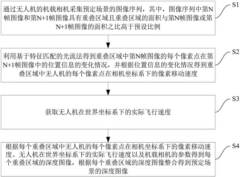
[0045] figure 1 It is a flowchart of a method for acquiring a depth image of a UAV according to an embodiment of the present invention. like figure 1 As shown, the method includes the following steps:

[0046] Step S1: the image sequence of the predetermined...


PUM


Abstract

The invention provides an unmanned aerial vehicle depth image acquisition method and an unmanned aerial vehicle. The method comprises the steps that an onboard camera is used to acquire the image sequence of a predetermined scene, wherein the Nth image and the N+1th image in the image sequence have overlapping areas and the area ratio of the area of each overlapping area to the area of the Nth image and the N+1th image is higher than a preset ratio; an optical flow method based on feature matching is used to acquire the change of the location information of each pixel of the Nth image in each overlapping area in the N+1th image, and accordingly the pixel movement speed of each pixel of the unmanned aerial vehicle in each overlapping area in a camera coordinate system is acquired; the actual flight speed of the unmanned aerial vehicle in a world coordinate system is acquired; and according to the pixel movement speed, the actual flight speed and the parameters of the onboard camera, the depth image of each overlapping area is acquired, and accordingly integrating is carried out to acquire the depth image of a predetermined scene. The method provided by the invention can be used to accurately acquire the depth images, and has the advantages of wide application scope, low cost and easy realization.

Description

technical field [0001] The invention relates to the technical field of image processing, in particular to a method for acquiring a depth image of an unmanned aerial vehicle and an unmanned aerial vehicle. Background technique [0002] The traditional imaging scheme is to convert the three-dimensional image model into a two-dimensional grayscale image, which loses the depth information of the image during the imaging process. However, the depth information of the image is very important for subsequent applications (such as three-dimensional reconstruction, geographic mapping, etc.). ), obtaining depth maps is of great significance for both theoretical research and engineering practice. [0003] Existing methods for acquiring depth images are generally active acquisition methods, which actively emit energy, such as lasers, electromagnetic waves, ultrasonic waves, etc., which are reflected by obstacles and then received; passive measurement includes methods based on machine vis...

Claims


Application Information

Patent Timeline
IPC IPC(8): G06T7/00B64D47/08
CPCG06T2207/30181G06T2207/10016B64U2101/30G06T7/00G06T7/579G06T7/55G06T7/269G06T7/60G06T5/00B64C39/024G05D1/0094G08G5/0069
Inventor 陈有生
Owner GUANGZHOU XAIRCRAFT TECH CO LTD
Learn More