Three-dimensional solid modeling method based on multi-contour-line triangularization network reconstruction
A technology of three-dimensional entities and modeling methods, which can be used in 3D modeling, image data processing, instruments, etc., and can solve problems such as unfavorable space analysis, slow calculation speed, and large storage space.
- Summary
- Abstract
- Description
- Claims
- Application Information
AI Technical Summary
Problems solved by technology
Method used
Image
Examples
Embodiment 1
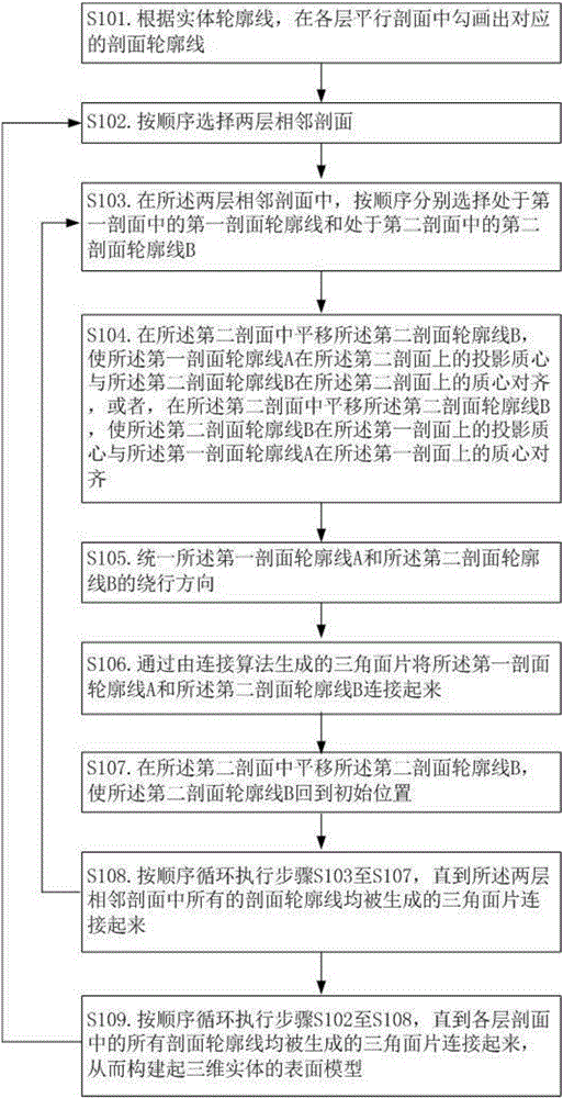
[0034] figure 1 A flow chart of the three-dimensional solid modeling method based on multi-contour triangulation reconstruction provided by the present invention is shown. The three-dimensional solid modeling method based on multi-contour triangulation network reconstruction includes the following steps.
[0035] S101. According to the outline of the entity, draw the corresponding section outline in the parallel sections of each layer.
[0036] S102. Select two adjacent sections in sequence.
[0037] S103. In the two adjacent sections, respectively select the first section contour line A in the first section and the second section contour line B in the second section in sequence.
[0038] S104. Translate the second profile line B in the second profile, so that the projected centroid of the first profile line A on the second profile and the second profile line B on the The centroids on the second section are aligned, or, in the second section, the second section contour line...
Embodiment 2
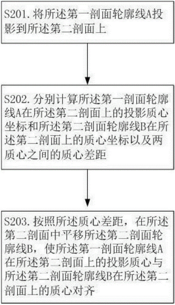
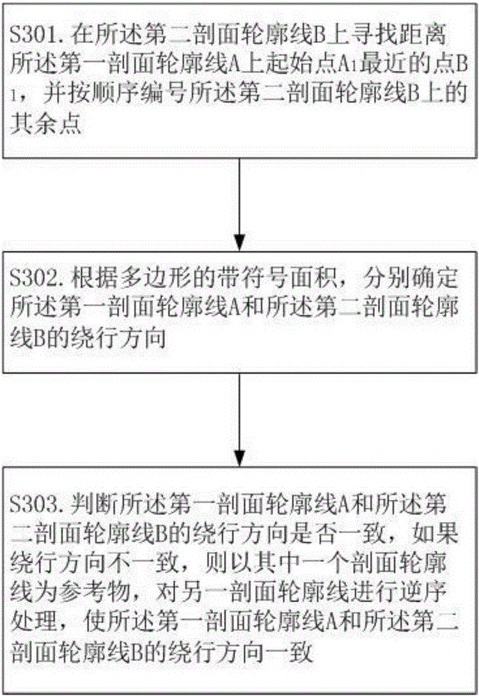
[0047] figure 2 It shows the flow chart of the method for aligning the centroid of section contour lines provided by the present invention, image 3 It shows the flow chart of the method for performing the directional consistency of section contour lines provided by the present invention, Figure 4A schematic diagram showing the detour direction of the contour line provided by the present invention, Figure 5 A schematic diagram of connecting triangular patches according to the shortest diagonal method provided by the present invention is shown. Embodiment 2 As a refinement scheme of Embodiment 1, each step in Embodiment 1 is described in detail below.
[0048] S101. According to the outline of the entity, draw the corresponding section outline in the parallel sections of each layer.
[0049] S102. Select two adjacent sections in sequence.
[0050] In step S102, the sections may be sorted and numbered according to the order of slicing the entity contours, and then the tri...
Embodiment 3
[0079] Image 6 It shows the flow chart of the error detection and error correction method for triangular patch intersection provided by the present invention, Figure 7 It shows the flow chart of the method for performing triangular surface intersection processing provided by the present invention, Figure 8 A schematic diagram showing the intersection relationship between two triangular faces provided by the present invention, Figure 9 It shows a schematic diagram of splitting the section contour line by adding auxiliary control lines provided by the present invention. Embodiment 3 As an optimization scheme of Embodiment 1 or Embodiment 2, the 3D solid modeling method based on multi-contour triangulation reconstruction provided by it is the same as the 3D solid modeling method provided in Embodiment 1 or Embodiment 2. The difference is that the following steps are also included before step S109.
[0080] S401. Perform triangular surface intersection processing on all tri...
PUM
 Abstract
Description
Claims
Application Information
 - R&D
- Intellectual Property
- Life Sciences
- Materials
- Tech Scout
- Unparalleled Data Quality
- Higher Quality Content
- 60% Fewer Hallucinations
Browse by: Latest US Patents, China's latest patents, Technical Efficacy Thesaurus, Application Domain, Technology Topic, Popular Technical Reports.
© 2025 PatSnap. All rights reserved.Legal|Privacy policy|Modern Slavery Act Transparency Statement|Sitemap|About US| Contact US: help@patsnap.com


