Dynode electron multiplier

A technology of electron multiplier and dynode, which is applied to the detailed information of electron multiplier, circuits, electrical components, etc., can solve the problems that restrict the development of space navigation technology, and achieve the effect of simple structure, stable performance and long life

Inactive Publication Date: 2016-01-06
LANZHOU INST OF PHYSICS CHINESE ACADEMY OF SPACE TECH
View PDF4 Cites 8 Cited by
  • Summary
  • Abstract
  • Description
  • Claims
  • Application Information

AI Technical Summary

Problems solved by technology

The lack of domestic high-performance space cesium atomic clock technology

Method used


Image

  • Dynode electron multiplier
  • Dynode electron multiplier
  • Dynode electron multiplier

Examples


Embodiment Construction

[0031] The present invention will be described in detail below in conjunction with the accompanying drawings. The description in this part is only exemplary and explanatory, and should not have any limiting effect on the protection scope of the present invention.

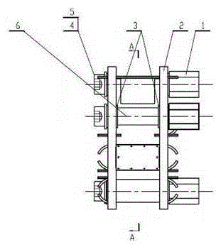
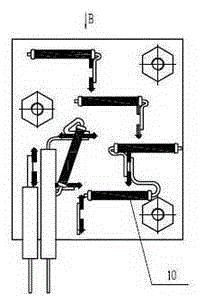
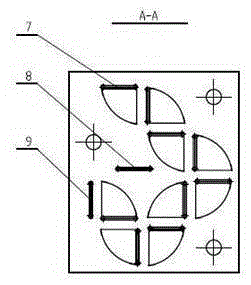
[0032] Such as Figures 1 to 5 A dynode electron multiplier shown includes two ceramic plates 2, several dynode assemblies 7, a transition piece assembly 8, a collection stage assembly 9 and several resistors 10,

[0033] The two ceramic plates 2 are arranged opposite to each other and connected by screws 5, and the transition piece assembly 8, the collection stage assembly 9 and several of the dynastage assemblies 7 are sandwiched between the two ceramic plates 2 and fixed on the ceramic plate 2. Above, each of the dynamite components 7 is connected in series in sequence, the first and last two dyna components 7 are respectively the first dyna level component 7 and the last dyna level component 7,

[0034] Also in...


PUM


Abstract

The invention discloses a dynode electron multiplier. The dynode electron multiplier comprises two ceramic plates, a plurality of dynode assemblies, a transitional part assembly, a collection level assembly and a plurality of resistors; the two ceramic plates are arranged in opposite and connected through screws; the transitional part assembly, the collection level assembly and the dynode assemblies are clamped between the two ceramic plates and fixed on the ceramic plates; the dynode assemblies are serially connected in sequence, and the dynode assembly at the head and the dynode assembly at the tail are the first level dynode assembly and the last level dynode assembly respectively; the dynode electron multiplier further comprises three leading wires; the first level dynode assembly is connected with one leading wire; the tail level dynode assembly and the transitional part assembly are connected with the second leading wire in sequence; the collection level assembly is connected with the third leading wire; the resistors are mounted on the outer side of the two ceramic plates; and each of the two ends of each dynode assembly is connected with one resistor in parallel. The dynode electron multiplier has the advantages of simple structure, long service life, stable property, low cost and the like.

Description

technical field [0001] The invention relates to the technical field of electron multiplier manufacture, in particular to a dynode electron multiplier. Background technique [0002] Atomic clocks are the core equipment for timekeeping and time service in various countries. They are widely used in military navigation and positioning systems, time-frequency measurement stations and time-frequency websites, and satellite civil navigation. They are one of the core loads of satellite navigation global positioning systems. At present, the relatively mature atomic clocks mainly include rubidium clocks, hydrogen clocks and cesium clocks. In comparison, cesium clocks have higher precision, the best long-term stability, and high reliability. There are very clear background requirements for space applications, such as navigation and deep space exploration. At the same time, a large number of small navigation system ground stations are used. cesium clock. [0003] The cesium clocks use...

Claims


Application Information

Patent Timeline
IPC IPC(8): H01J43/04H01J9/00
Inventor 李晨李得天王多书张玲曹生珠
Owner LANZHOU INST OF PHYSICS CHINESE ACADEMY OF SPACE TECH
Why Eureka
Try Eureka