Check patentability & draft patents in minutes with Patsnap Eureka AI!

Sensor device

A sensor device and sensor technology, applied in the direction of measuring devices, instruments, scientific instruments, etc., can solve the problem of high investment in the protective cover system, and achieve the effects of optimized flow distribution, good thermal shock resistance, and simple manufacturing

Inactive Publication Date: 2016-01-06
CONTINENTAL AUTOMOTIVE GMBH
View PDF6 Cites 1 Cited by
  • Summary
  • Abstract
  • Description
  • Claims
  • Application Information

AI Technical Summary

Problems solved by technology

[0008] These shield systems are very costly

Method used


Image

  • Sensor device
  • Sensor device
  • Sensor device

Examples


Embodiment Construction

[0033] Elements of the same structure or function are marked with the same reference numerals in all figures.

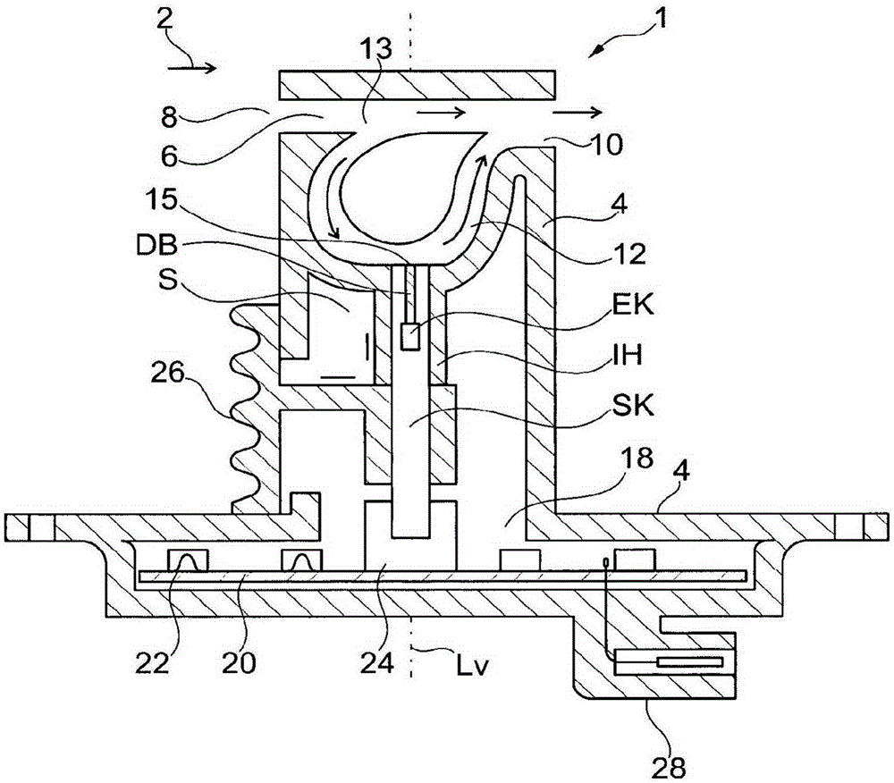
[0034] figure 1 Shown is a sensor device 1 which is arranged in the main channel. The main gas stream 2 flows in the main channel. The main channel can be, in particular, an intake line in an internal combustion engine, through which an aspirated air flow flows.

[0035] The sensor device 1 comprises a housing 4 . A flow channel 6 is provided in the housing 4 and has an inlet opening 8 and an outlet opening 10 . The flow channel 6 can be linear in the housing 4 , for example, and is preferably arranged by means of the orientation of the housing 4 such that its inlet opening 8 faces in the opposite direction with respect to the main flow direction of the air mass flowing from the side.

[0036] The sensor device 1 has a device longitudinal axis L V . Furthermore, the sensor device 1 has a first end region and a second end region. The flow channel 6 is arranged ...


PUM


Abstract

The sensor device (1) comprises a housing body (4), which has a flow channel (6) formed in the housing body (4). Furthermore, the sensor device (1) has a bypass (12) formed in the housing body (4), which bypass branches off from the flow channel (6) at a branching point (13). The bypass (12) has a wall having an opening. Furthermore, the sensor device (1) comprises a sensor element (S) for detecting a gas content in an environment of the sensor element (S), which is arranged at least partially in the opening in the wall of the bypass (12). The sensor element (S) is designed to detect a gas content in an environment of the sensor element (S). The sensor element (S) comprises a sensor body (SK). The sensor element (S) also comprises an electrode chamber (EK), which is formed in the sensor body (SK). The sensor element (S) comprises a heating element, which is embedded in the sensor body (SK), by means of which heating element a specified region around the electrode chamber (EK) can be heated to a specified operating temperature. The sensor element (S) has a longitudinal axis. Furthermore, the sensor element (S) comprises an inlet channel (EAK), which is coupled to the electrode chamber (EK) and which has an inlet (EA) at the surface of the sensor body (SK). Furthermore, the sensor element (S) comprises a thermal insulation sleeve (IH) on the sensor body (SK), which thermal insulation sleeve extends at least axially in the direction of the longitudinal axis over the region of the electrode chamber (EK).

Description

technical field [0001] The invention relates to a sensor device comprising a sensor element for detecting a gas content in the environment of the sensor device. Background technique [0002] Gas sensors, in particular oxygen sensors, are used in the intake tract or exhaust tract of internal combustion engines, for example gasoline or diesel engines. Such an oxygen sensor is, for example, a linear lambda sensor. Most lambda sensors of this type have a sensor element which has to be heated to approximately 800° C. [0003] For exhaust gas sensors, use housings suitable for high temperatures. The exhaust gas sensor has a protective cover system which, in addition to providing mechanical protection, mainly has the following tasks: [0004] - Guaranteed gas exchange at the gas inlet of the measuring cell, [0005] - protected against cooling under high gas flows, [0006] - be protected against small water droplets, and [0007] -Protect from water shock. [0008] These sh...

Claims


Application Information

Patent Timeline
IPC IPC(8): G01N27/407G01N33/00
CPCG01N27/4077G01M15/104G01N27/407G01N27/4078
Inventor J·安特P·格拉斯
Owner CONTINENTAL AUTOMOTIVE GMBH
Features
  • R&D
  • Intellectual Property
  • Life Sciences
  • Materials
  • Tech Scout
  • Unparalleled Data Quality
  • Higher Quality Content
  • 60% Fewer Hallucinations
Learn More