
High precision peristaltic pump control method

A control method, peristaltic pump technology, applied in the direction of the device introduced into the body, pressure infusion, etc., can solve the problems of low stability, high delay, easy to exceed, etc., to improve accuracy and stability, overcome fluctuation interference, The effect of the difficult backflow phenomenon

Inactive Publication Date: 2018-12-25
CHONGQING TECH & BUSINESS INST
View PDF3 Cites 0 Cited by
  • Summary
  • Abstract
  • Description
  • Claims
  • Application Information

AI Technical Summary

Problems solved by technology

The conventional peristaltic pump control system can only adjust the accumulative speed of the peristaltic pump for one cycle, and cannot adjust the angular velocity of the peristaltic pump.
[0003] The traditional peristaltic pump is limited by the structure. When the pump is running at different angles, the resistance it receives is inconsistent, resulting in an unstable speed. Therefore, the pump will generate a pulse flow during operation, which will cause a large change in the pressure in the pipeline. The pulsating flow generated by the peristaltic pump also appears backflow phenomenon, which affects the stability of the pressure and flow in the pump tube, easily exceeds the alarm line of the blood purification equipment, and affects the comfort of the patient's treatment.
The existing peristaltic pump control system performs control based on the collected peristaltic pump speed superimposed with the preset control signal amount, but basically does not process the collected data, resulting in high delay, slow response, and adaptability in the control of the peristaltic pump. In recent years, in the actual measurement and control, how to ensure the real-time precise control of the peristaltic pump is an urgent problem to be solved.

Method used


Image

  • High precision peristaltic pump control method
  • High precision peristaltic pump control method

Examples


Embodiment Construction

[0024] Below in conjunction with accompanying drawing and embodiment the present invention will be further described:

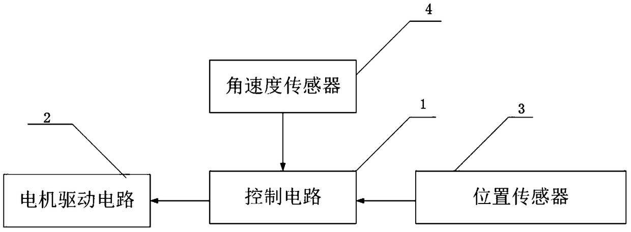
[0025] like figure 1 As shown, a peristaltic pump control system includes a control circuit 1, a motor drive circuit 2, a position sensor 3 and an angular velocity sensor 4; the output end of the control circuit 1 is connected to the input end of the motor drive circuit 2; the control circuit The first input end of the control circuit 1 is connected to the signal output end of the position sensor 3 ; the second input end of the control circuit 1 is connected to the signal output end of the angular velocity sensor 4 .

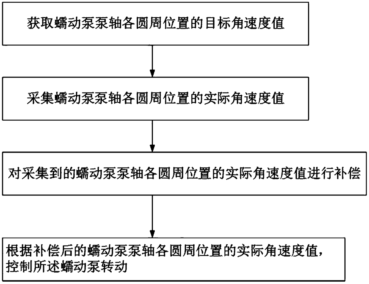
[0026] like figure 2 As shown, a high-precision peristaltic pump control method is carried out by using the peristaltic pump control system according to the following steps:

[0027] Step 1, the control circuit 1 outputs a fixed control signal to the motor drive circuit 2 to control the rotation of the peristaltic pump; the position sensor 3...


PUM


Abstract

The invention discloses a high-precision peristaltic pump control method, and relates to the field of automation control. Through compensation of an acquired magnitude of angular velocity, fluctuation interference caused by chance factors can be overcome effectively, and an accurate angular velocity acquiring unit value is provided for follow-up data processing. The acquired magnitude of angular velocity is compensated through computing of a compensating parameter of the magnitude of angular velocity. Because the magnitude of angular velocity acquired by the traditional peristaltic pump control system has large deviation and dynamic responsiveness is poor, the trend of change of the angular velocity cannot be considered fully, and the magnitude of angular velocity has to be compensated. By the parameter and mode for compensating the magnitude of angular velocity in the technical scheme, the acquired magnitude of angular velocity can be compensated dynamically according to the acquired magnitude of angular velocity and the trend of change of the angular velocity, so that the adjusting amount of the angular velocity can be accurately judged in advance, and accuracy and stability of peristaltic pump control are improved.

Description

technical field [0001] The invention relates to the field of automatic control, in particular to a high-precision peristaltic pump control method. Background technique [0002] Peristaltic pumps are widely used in blood purification equipment due to their advantages of no pollution, high precision, and good sealing. The conventional peristaltic pump control system can only adjust the accumulative speed of the peristaltic pump for one round of operation, but cannot realize the adjustment of the angular velocity of the peristaltic pump. [0003] The traditional peristaltic pump is limited by the structure. When the pump is running at different angles, the resistance it receives is inconsistent, resulting in an unstable speed. Therefore, the pump will generate a pulse flow during operation, which will cause a large change in the pressure in the pipeline. The pulsating flow generated by the peristaltic pump also has a backflow phenomenon, which affects the stability of the pres...

Claims


Application Information

Patent Timeline
Patent Type & Authority Patents(China)
IPC IPC(8): A61M5/142
Inventor 廖妍秦晓琴
Owner CHONGQING TECH & BUSINESS INST
Learn More