
Filter bag dust remover with self-circulating ash removal device

A technology of dust cleaning device and dust collector, which is applied in the direction of dispersed particle filtration, chemical instruments and methods, and separation of dispersed particles. Induced fan load and other issues to achieve the effect of ensuring the blowing effect, reliable operation, and prolonging the life of the filter bag

Active Publication Date: 2016-01-13
岳波
View PDF11 Cites 15 Cited by
  • Summary
  • Abstract
  • Description
  • Claims
  • Application Information

AI Technical Summary

Problems solved by technology

Filter bag service life is reduced, usually no more than 3 years
[0012] d. Due to the installation of the nozzle above the filter bag for the blown dust collector, it is extremely inconvenient to replace the filter bag and bag cage
[0013] e. The dust collector of line blowing adopts a circular filter bag to occupy a large area and the volume of the dust collector is large; although the dust collector of the rotary jet is a flat filter bag, it adopts an overall circular arrangement, and the volume of the four corners is wasted. The volume is also large;
[0014] f. The most critical thing is that the purge air source enters the dust collector, which increases the load of the induced draft fan of the boiler and increases the energy consumption
And produce fluctuating load (large when purging, small when not purging)

Method used


Image

  • Filter bag dust remover with self-circulating ash removal device
  • Filter bag dust remover with self-circulating ash removal device
  • Filter bag dust remover with self-circulating ash removal device

Examples


Embodiment Construction

[0038] The present invention will be described in detail below in conjunction with the embodiments shown in the accompanying drawings.

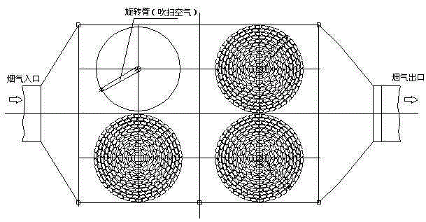
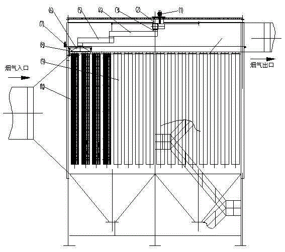
[0039] The self-circulation dust removal filter bag dust collector of the present invention includes a basic support, an air flow uniform distribution and flow guide device, a filter bag room, a clean air room, filter components (filter bags, bag cages, flower plates, etc.), and a self-circulation dust removal system. , ash hopper, electrical control system, insulation layer, platform, stairs, and a pre-painted ash system.

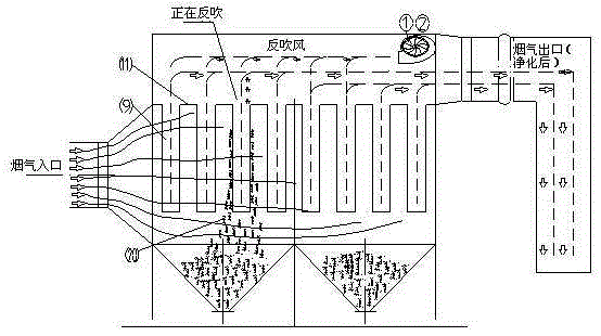
[0040] See image 3 , Schematic diagram of the working principle of the self-circulating dust-cleaning filter bag filter.

[0041] Among the figure: motor 1, centrifugal fan 2, filter bag 9, flower plate 11, dust 20.

[0042]The dust-laden flue gas from the boiler air preheater enters the bag filter through the flue at the flue gas inlet, and under the negative pressure of the induced draft fan, the flue gas enters the ...


PUM


Abstract

The invention relates to a dust remover, and concretely relates to a filter bag dust remover with a self-circulating ash removal device. The dust remover comprises a base support, an airflow uniform distribution and flow guiding device, a filter bag chamber, an air purifying chamber, a filtering assembly, a self-circulating ash removal system, an ash bucket, an electric control system, a heat insulation layer, a platform, a stair and a pre-coating system; an air inlet is provided with the airflow uniform distribution and flow guiding device, forward and upward airflow channels are arranged in a bag zone, filter bags are arranged in a rectangular chamber in groups, the mouths of a plurality of the filter bags are compressed through bolts through a steel plate to make the filter bags be firmly clamped in the hole of a tube sheet, the tube sheet is provided with a filter bag hole, a hole plate is smooth without burrs, and the filter bags form a double sealing structure at the upper portion of the tube sheet and in the hole of the tube sheet. The dust remover adopting low pressure air generated by a centrifuge fan to purge in order to close and leakage-free ash removal has the advantages of blowing effect guaranteeing, no light damages to the filter bags, and safe and reliable running, and adopts programmed control to purge row by row in sequence in order to realize the ash removal purpose.

Description

technical field [0001] The invention relates to a dust collector, in particular to a filter bag type dust collector with a self-circulation dust removal device. Background technique [0002] Filter bag dust collector is the mainstream technology for flue gas dust removal in coal-fired power plant boilers. It is composed of ash hopper and electrical control system. [0003] The working principle of the filter bag dust collector is: the dusty flue gas from the boiler enters the filter bag dust collector through the flue of the flue gas inlet, and under the negative pressure of the boiler induced draft fan installed behind the dust collector, the dusty flue gas passes through and The air intake bell of the dust collector enters the bag filter, and passes through the air distribution plate of the filter bag filter to ensure the flow distribution of the flue gas before entering the filter bag bundle, avoiding the local dust-laden gas flow rate that is too fast to cause damage to...

Claims


Application Information

Patent Timeline
IPC IPC(8): B01D46/02B01D46/04
Inventor 岳鹏岳波
Owner 岳波
Learn More