
Slurry recycling and stirring tank

A recovery tank and mixing tank technology, applied in the high-density fiberboard production line and fiber slab field, can solve the problems of lack of reliability of the equipment, and achieve the effect of simple structure and stable and reliable operation of the equipment

Inactive Publication Date: 2016-01-13
河南鑫饰板业有限公司
View PDF4 Cites 0 Cited by
  • Summary
  • Abstract
  • Description
  • Claims
  • Application Information

AI Technical Summary

Problems solved by technology

The water sealing parts of the above structure need to be inspected and tightened or replaced regularly, and the equipment lacks operational reliability

Method used


Image

  • Slurry recycling and stirring tank
  • Slurry recycling and stirring tank

Examples


Embodiment Construction

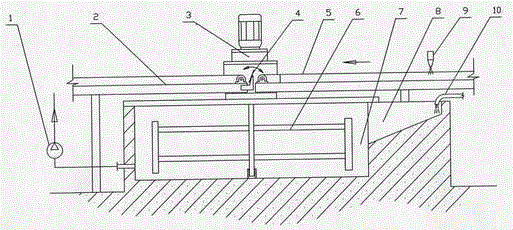
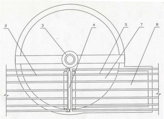
[0008] The embodiment is described in detail in conjunction with the above drawings. The electromagnetic flipper 4 is arranged in the middle of the slab conveying platform 2 and another slab conveying platform 5, and the slab conveying platform 2 and the other slab conveying platform 5 pass through the support fixed, the bottom of the electromagnetic flapper is provided with a slurry recovery tank 7, a vertical agitator 6 is arranged in the slurry recovery tank, and a coupling is used between the stirring reduction motor 3 and the agitator, and the slurry The profile of the material recovery tank is circular, and the front of the said slurry recovery tank is the edge-aligned slurry recovery tank 8, and the bottom of the said edge-aligned recovery tank is a square with a slanted bottom. Further, the length of the edge-aligned recovery tank extends to The lower part of the trimming spray nozzle 9 is water-cut, so as to collect the waste fiber slurry of the trimming slab, and the ...


PUM


Abstract

The invention discloses a slurry recycling and stirring tank which includes an electromagnetic turning plate device. The electromagnetic turning plate device is arranged in the middle between two plate blank transportation benches. A slurry recycling tank is arranged on the lower part of the electromagnetic turning plate device. A vertical stirrer is disposed in the slurry recycling tank. A stirring gear motor and a stirrer are connected to each other through a coupler. An edge-leveled slurry recycling tank is arranged in the front of the slurry recycling tank, wherein the bottom of the edge-leveled slurry recycling tank is inclined and squared in shape. A diluting water pipe is arranged at the end of the edge-leveled slurry recycling tank. A slurry recycling pump is connected to a side of the slurry recycling tank. The slurry recycling and stirring tank is simple in structure and is stable and reliable in operation, and can be widely used in production of high-density fiber plates.

Description

technical field [0001] The invention relates to a stirring tank for slurry recovery, which is especially suitable for high-density fiberboard production lines, especially for use on fiberboard blanks formed by fourdrinier laying. Background technique [0002] In the existing high-density fiberboard production line, for the fiber slabs formed by fourdrinier laying, if there are unqualified or defective slabs, the electromagnetic flipper needs to be turned on, and the fiber slabs are turned into the slurry recovery mixing tank for dilution and recycling , usually the slurry recovery stirring tank is set under the electromagnetic turnover device, the slurry recovery stirring tank is usually a square structure, the stirring shaft is horizontal, the stirring shaft is immersed in the liquid slurry tank, and the shaft heads at both ends of the stirring shaft are provided with packing Or other water sealing parts to prevent the dilution water in the slurry tank from leaking along th...

Claims


Application Information

Patent Timeline
IPC IPC(8): B01F7/16
Inventor 戚世军曹宗宇李来平
Owner 河南鑫饰板业有限公司
Learn More