Punching machine for machining piston assemblies used for automobile brakes

A technology for piston parts and automobile brakes, applied in the field of mechanical forging, can solve problems such as die wear and tear, and achieve the effects of improving die strength, increasing die life, and improving work efficiency.

Active Publication Date: 2016-01-13
浙江铭锐金属制品股份有限公司
View PDF6 Cites 0 Cited by
  • Summary
  • Abstract
  • Description
  • Claims
  • Application Information

AI Technical Summary

Problems solved by technology

[0003] The purpose of the present invention is to solve the problem of early wear and tear of the mold due to the local stress of the mold i

Method used


Image

  • Punching machine for machining piston assemblies used for automobile brakes
  • Punching machine for machining piston assemblies used for automobile brakes
  • Punching machine for machining piston assemblies used for automobile brakes

Examples


Example Embodiment

[0027] Embodiment one

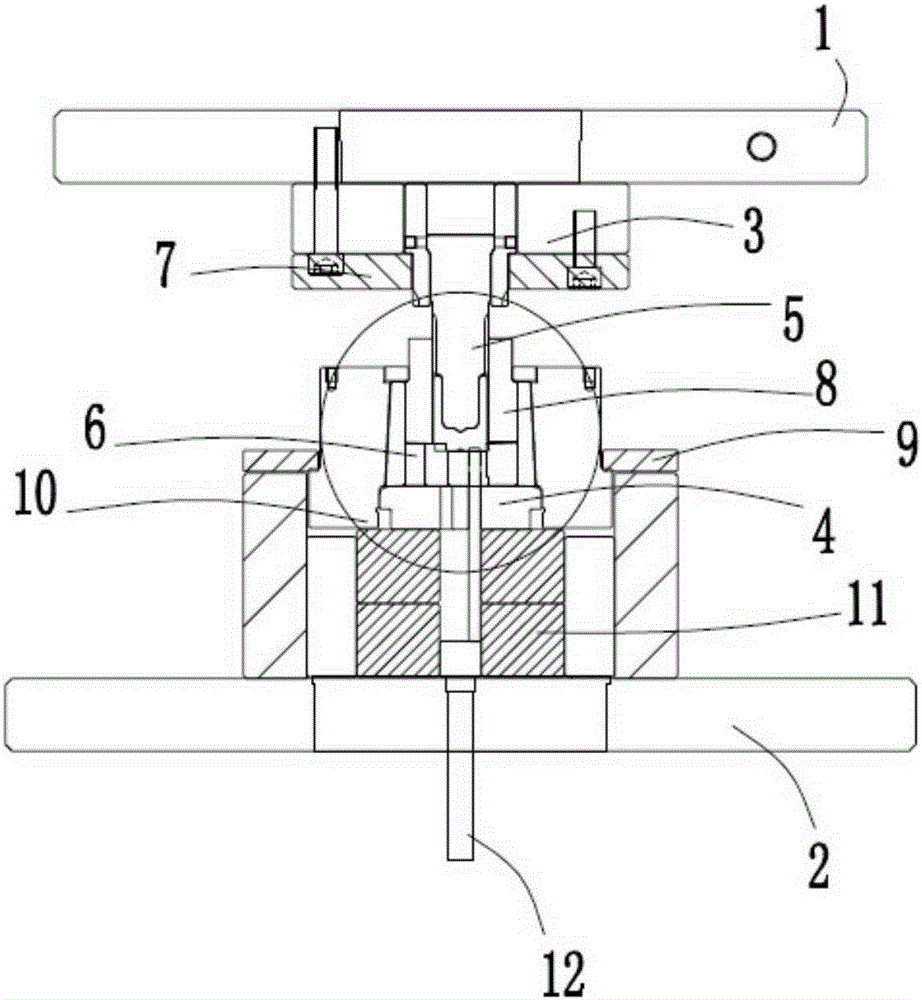
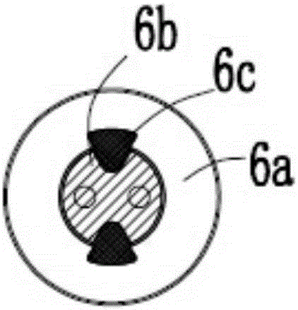
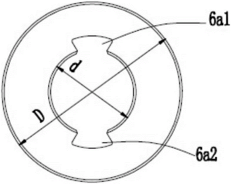
[0028] Picture 1-1 Schematic diagram of embodiment one for processing stamping machine for piston parts for automobile brakes, Figure 1-2 Partially enlarged top view schematic diagram of the lower mold of the stamping machine for the piston parts of the automobile brake, figure 2 It is a schematic diagram of the outer ring mold 6a of the lower mold in embodiment two, image 3 It is a schematic diagram of the inner ring mold 6b of the lower mold in embodiment two, Figure 4 It is a schematic diagram of the connecting key 6c of the lower mold in the second embodiment. like Picture 1-1 , Figure 1-2 , figure 2 , image 3 and Figure 4 As shown, what is provided in this embodiment is a stamping machine for processing piston parts for automobile brakes, including an upper body 1, a lower body 2, an upper mold base 3, a lower mold base 4, an upper mold 5, a lower mold 6, and a fixing plate 7. Side pressure block 8, limit sleeve 9, guide post 10, b...


PUM


Abstract

The invention relates to a punching machine for machining piston assemblies used for automobile brakes. The punching machine comprises an upper machine body, a lower machine body, an upper die base, a lower die base, an upper die, a lower die, fixing plates, side pressing blocks, a limiting sleeve, a guide column, a bearing table and an ejector rod. The side pressing blocks are fixedly connected with the lower die. The limiting sleeve is fixedly connected to the outer side of the guide column. The guide column is fixedly connected to the two sides of the side pressing blocks. The upper die base is fixedly connected to the upper machine body. The lower die base is fixedly connected to the bearing table. The bearing table is fixedly connected to the lower machine body. The lower die is placed between the side pressing blocks and the lower die base. The lower die comprises an outer die body, an inner die body and connecting keys. The interior of the outer die body is provided with two grooves. The edge of the inner die body is provided with two notches. Each connecting key is triangular. The grooves of the outer die body correspond to the notches of the inner die body. The inner die body is connected with the outer die body through the connecting keys. The ejector rod is fixed to the center of the lower machine body and penetrates through the lower machine body, the bearing table, the lower die base and the lower die. By means of the punching machine, the problems that the lower die is prone to cracks and short in service life are solved, the service life of the lower die is prolonged, and working benefits are increased.

Description

technical field [0001] The invention relates to the field of mechanical forging, in particular to a stamping machine for processing piston parts for automobile brakes. Background technique [0002] As a kind of forging equipment, the stamping machine is often widely used in the mold casting process. It relies on the stamping machine and the mold to exert external force on the plate-shaped strip, so that the strip can be plastically deformed or separated, so as to obtain the stamping of the required shape and size. pieces. Stamping includes two kinds of deformation process and separation process. The separation process is also called blanking. Its purpose is to separate the stamped parts from the strip along a certain contour line, while ensuring the quality requirements of the separation section. The purpose of the forming process is to make the strip plastically deform without breaking the billet to make a blank of the required shape and size, but the use of the punching m...

Claims


Application Information

Patent Timeline
IPC IPC(8): B21J13/02B21J9/02
Inventor 许峰
Owner 浙江铭锐金属制品股份有限公司
Why Eureka
Try Eureka