
A device and method for laying reinforcing fiber filaments for the production of composite grids

A technology of reinforcing fibers and composite materials, applied in the field of composite grid production equipment and technology, can solve the problems of high cost of mold equipment, high labor intensity, low production efficiency, etc., to improve versatility and utilization, and reduce labor intensity. , the effect of improving production efficiency

Inactive Publication Date: 2017-07-07
南京申瑞电力电子有限公司
View PDF8 Cites 0 Cited by
  • Summary
  • Abstract
  • Description
  • Claims
  • Application Information

AI Technical Summary

Problems solved by technology

[0003] At present, the production of composite grid products is prepared by molding in a single grid mold, and the reinforcement fiber laying on the mold is carried out manually, and there is a problem of high labor intensity. , low production efficiency, high labor costs, large waste of materials, etc.
The main reasons why the laying of reinforcing fibers in the production process of the new composite material grid can only be done manually are: the existing automatic production equipment cannot match the existing mold equipment, and the mold equipment must be re-equipped during production. However, the cost of mold equipment is very expensive, so that automatic production equipment cannot be well used in the actual production process

Method used


Image

  • A device and method for laying reinforcing fiber filaments for the production of composite grids
  • A device and method for laying reinforcing fiber filaments for the production of composite grids
  • A device and method for laying reinforcing fiber filaments for the production of composite grids

Examples


Embodiment Construction

[0023] The present invention will be further explained below in conjunction with the accompanying drawings.

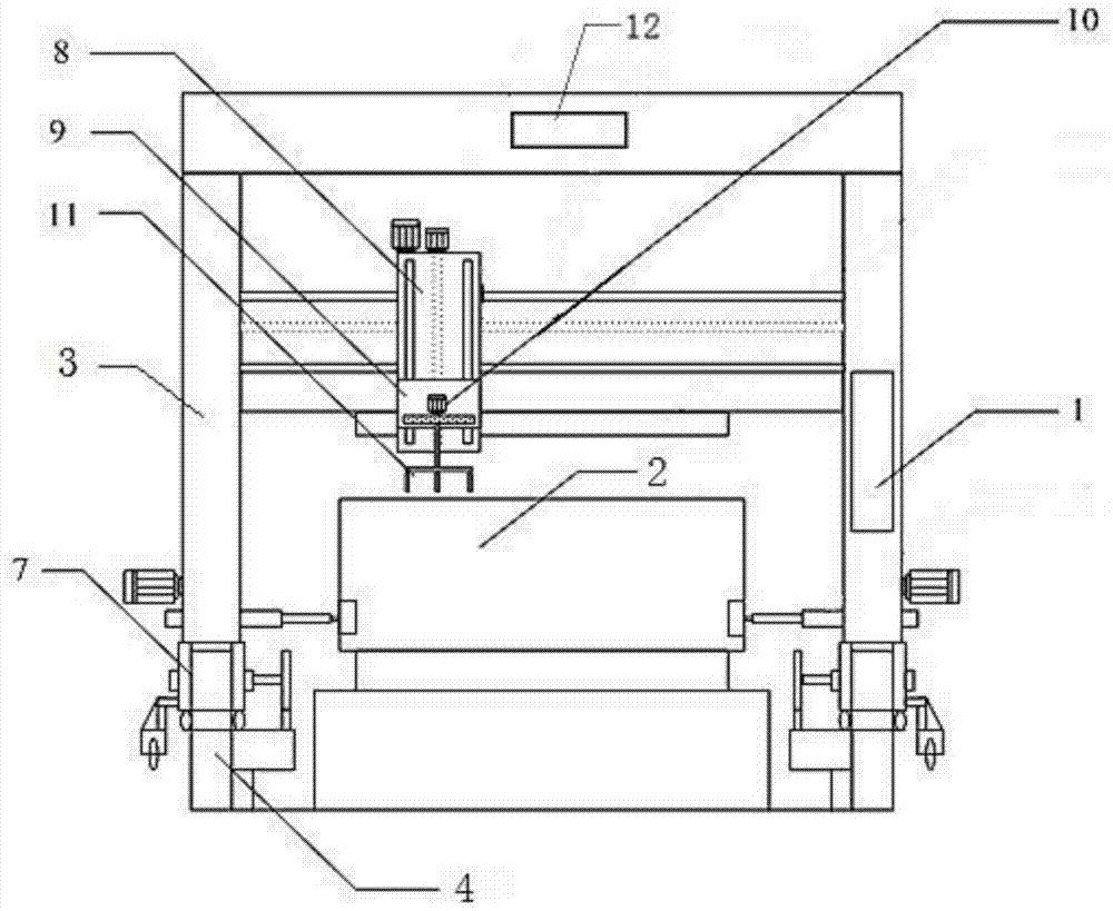
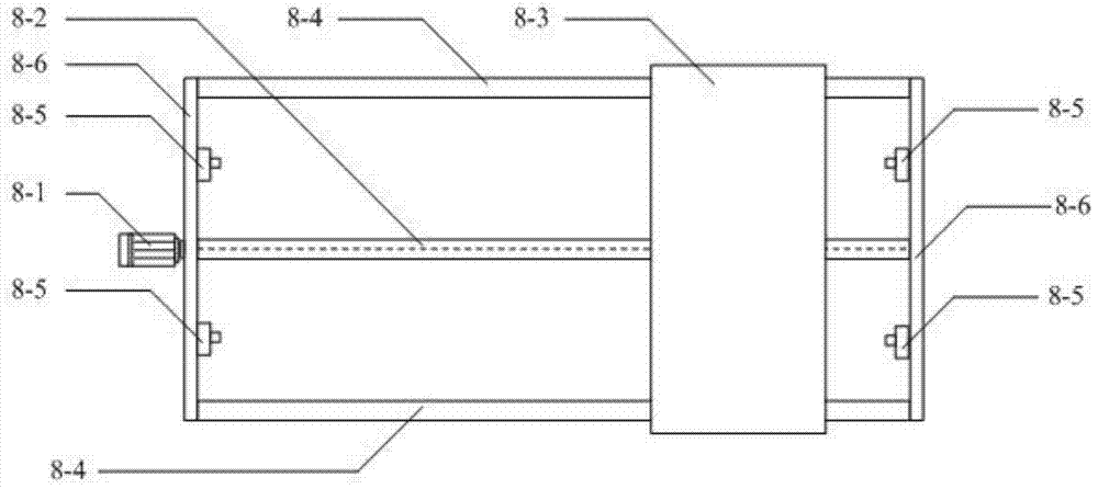
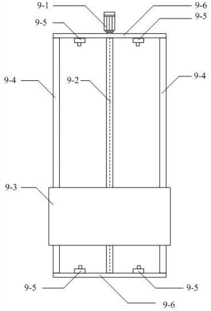
[0024] Such as figure 1 As shown, the reinforcing fiber yarn laying device for composite grid production of the present invention includes a mold table 2, a gantry frame 3, a track 4, a walking wheel 7, a sliding table mechanism 8, an elevating table mechanism 9, a rotary table Mechanism 10, laying head 11, wire feeding mechanism 12 and computer control system 1. Rails 4 are laid on both sides of the mold platform 2, and the gantry-shaped vehicle frame 3 spans over the mold platform 2, and the bottom of the gantry-shaped vehicle frame 3 is provided with a traveling wheel 7, which drives the gantry-shaped vehicle frame 3 along the Move on track 4. The gantry frame 3 is provided with a computer control system 1, a slide mechanism 8 and a wire supply mechanism 12, the slide mechanism 8 is provided with a lift mechanism 9, and the lift mechanism 9 is provided with a turn...


PUM


Abstract

The invention discloses a reinforced fiber silk laying device and method used for producing a grating made of a composite material. The device comprises a die table, rails are laid on the two sides of the die table, a gantry type frame stretches over the die table, and running wheels are arranged at the bottom of the gantry type frame. The gantry type frame is driven to move along the rails through the running wheels, and the gantry type frame is provided with a computer control system, a sliding table mechanism and a silk supply mechanism. The sliding table mechanism is provided with a lifting table mechanism. The lifting table mechanism is provided with a rotary table mechanism. A work head is laid on the rotary table mechanism. The computer control system is connected with the running wheels, the sliding table mechanism, the lifting table mechanism, the rotary table mechanism and the silk supply mechanism. According to the method, the device is used for achieving reinforced fiber laying work on the die worktable. By means of the device and method, the process mode that reinforced fiber laying is completed manually is changed, flexible reversing of laying of multiple sets of fiber silk can be completed, and production requirements of rectangular grating die tables in different sizes are met.

Description

technical field [0001] The invention relates to a composite material grid production equipment and process, in particular to a reinforcement fiber filament laying device and method for composite material grid production. Background technique [0002] Composite grid is formed by interweaving reinforcing fibers, resin pouring, heat fusion, and overall molding. It is a composite material sheet with many regularly distributed rectangular or square grids. It has the mechanical characteristics of bidirectional isotropy, light weight, high strength, anti-aging, long life, low thermal conductivity, good insulation, and corrosion resistance of acid, alkali, organic solvents and salts. [0003] At present, the production of composite grid products is prepared by molding in a single grid mold, and the reinforcement fiber laying on the mold is carried out manually, and there is a problem of high labor intensity. , low production efficiency, high labor costs, large waste of materials an...

Claims


Application Information

Patent Timeline
Patent Type & Authority Patents(China)
IPC IPC(8): B29C70/30
CPCB29C70/30
Inventor 申明顾云俊谢沛欣
Owner 南京申瑞电力电子有限公司
Learn More