
Reversing speed reducer

A speed reducer and positive rotation technology, which is applied in the direction of mechanical equipment, mining fluid, gear transmission, etc., can solve the problems of energy-saving effect reduction, inability to achieve precise balance, and decline in mechanical efficiency of beamless pumping units, and achieve improved Mechanical transmission efficiency, simple structure, and the effect of reducing the loss of mechanical efficiency

Inactive Publication Date: 2016-01-13
杨靖康
View PDF7 Cites 7 Cited by
  • Summary
  • Abstract
  • Description
  • Claims
  • Application Information

AI Technical Summary

Problems solved by technology

A typical beam pumping unit is a four-link structure, which uses a four-link mechanism to convert the one-way circular motion of the motor into a reciprocating linear motion of the suspension point. The main disadvantage of this structure is that it consumes less energy The second is that it is not suitable for a long stroke, and the third is that it cannot achieve precise balance, resulting in high motor configuration, large horse-drawn and small carts
[0005] Reversing reducers with various mechanisms are constantly being designed. The more reasonable ones are the reversing reducers designed by ZL201120297063.X and document CN104295711A, but the structure is slightly complicated and there are many transmission gears, which will naturally reduce the mechanical efficiency. , so that the energy-saving effect of the beamless pumping unit is discounted

Method used


Image

  • Reversing speed reducer
  • Reversing speed reducer
  • Reversing speed reducer

Examples


Embodiment Construction

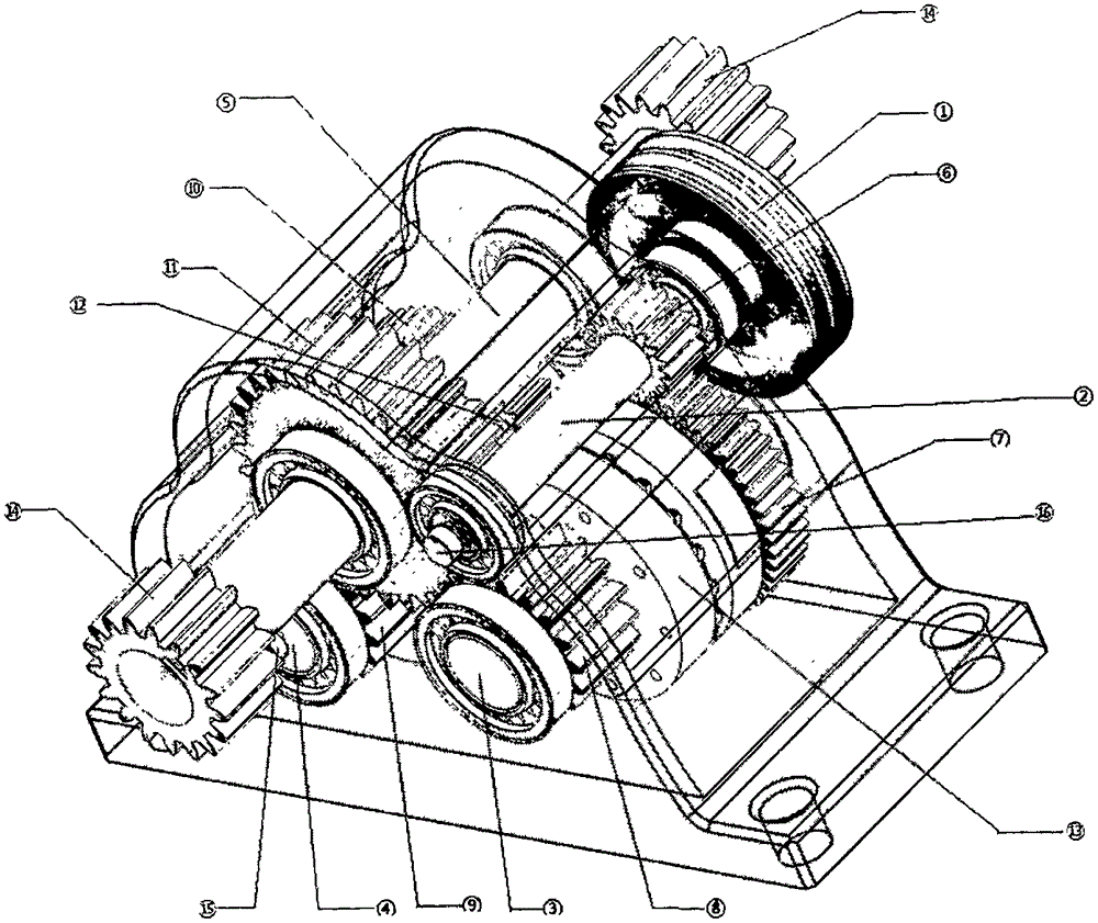
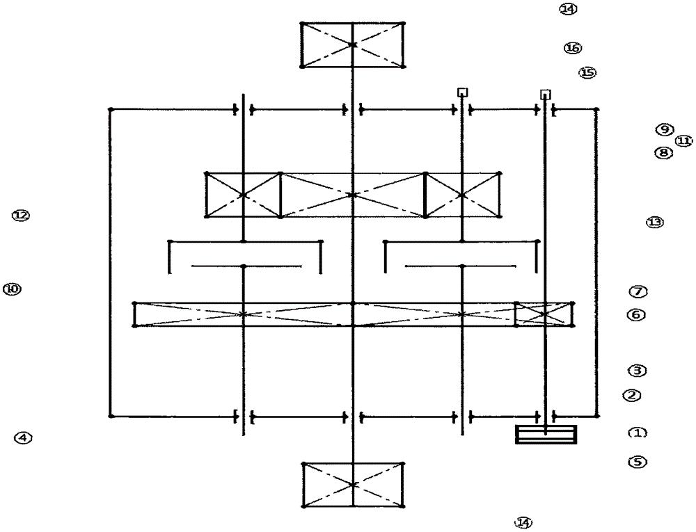
[0022] figure 1 There are four shafts in total, namely: power input shaft 2, intermediate shaft 3, intermediate shaft 4, and power output shaft 5. They are respectively fixed on the casing of the machine through bearings.

[0023] figure 1 Two groups of clutches (12, 13) are used in the middle, and every group of clutches is divided into two parts again, is combined or separated by mechanism driving.

[0024] figure 1 One end of the pulley 1 is connected to the power source motor (omitted in the figure), the other end is fixed to the input shaft 2, the input shaft 2 is fixed to the driving gear 6, and the driving gear 6 is in phase with the input gear 7 of the intermediate shaft fixed on the intermediate shaft 3. meshing, the input gear 7 of the intermediate shaft 3 meshes with the input gear 10 of the intermediate shaft 4; when the power source motor rotates in a certain direction, the driving gear 6 drives the gear 7 to rotate, 7 drives the 10 to rotate, and the speed of ...


PUM


Abstract

The invention provides a long-stroke mechanical reversing speed reducer capable of being used for an oilfield oil pumping unit. Under the condition that a motor rotates in a specific direction, an output shaft can achieve forward and reverse rotation according to a certain rule through the reversing speed reducer, and therefore an oil pumping rod can reciprocate up and down linearly. According to the reversing speed reducer, two intermediate shafts (including one forward rotating intermediate shaft and one reverse rotating intermediate shaft) are mainly utilized, through cooperation and alternate combination and separation of two clutches, power passes through the two intermediate shafts in turn to be transmitted to the output shaft from an input shaft, and therefore the forward and reserve rotation reserving function can be achieved. In the power transmitting process, through combination of size changes of gears, the purposes of reducing speed and increasing torque are achieved. An encoder for metering angular displacement is arranged on the reserving speed reducer, and the encoder can be utilized for accurately metering the rotating angle of the output shaft so that accurate reversing can be achieved. Besides, by means of the function of the encoder, the clutches can be combined when the rotation speed difference of half shafts is closest, and therefore impacting and abrasion generated when the clutches are combined can be reduced.

Description

technical field [0001] The invention relates to oil field mechanical oil production equipment, in particular to a reversing speed reducer used for a long-stroke pumping unit that does not rely on the forward and reverse reversing of a motor. It is also suitable for other machines that require forward and reverse or reciprocating linear motion. Background technique [0002] The pumping unit of prior art is divided into two kinds of beam pumping unit and no beam pumping unit. A typical beam pumping unit is a four-link structure, which uses a four-link mechanism to convert the one-way circular motion of the motor into a reciprocating linear motion of the suspension point. The main disadvantage of this structure is that it consumes less energy The second is that it is not suitable for a long stroke, and the third is that it cannot achieve precise balance, resulting in high motor configuration, large horses and small carts. [0003] Beamless pumping unit is the development tren...

Claims


Application Information

Patent Timeline
IPC IPC(8): F16H3/14F16H57/00E21B43/12
CPCF16H3/14E21B43/121F16H57/00
Inventor 杨靖康
Owner 杨靖康
Learn More