Metal hydride hydrogen storage and fuel cell combined system

A fuel cell system and fuel cell technology, applied in the direction of fuel cells, fuel cell additives, fuel cell heat exchange, etc., can solve the problems of many power-consuming equipment, different applicable designs, and large poisoning risks, so as to improve cooling performance, The effect of simplification of cooling channels

Active Publication Date: 2017-08-25
GRIMAT ENG INST CO LTD
View PDF1 Cites 0 Cited by
  • Summary
  • Abstract
  • Description
  • Claims
  • Application Information

AI Technical Summary

Problems solved by technology

However, the technologies disclosed in the above-mentioned patent documents are mainly designed for vehicle-mounted fuel cell systems, which use too many power-consuming devices and are not suitable for base station emergency backup power systems. In addition, the different selection criteria for hydrogen storage alloys also lead to suitable design For example, the hydrogen storage system in the patent literature mainly uses light-weight Mg-based hydrogen storage alloys, and the required hydrogen depletion temperature of 300 ° C is the time required for heating up and the additional energy consumption for the emergency power fuel cell system used in base stations. It is not applicable to the fuel cell backup power system of the base station in the state of emergency power failure
The anti-poisoning performance of hydrogen storage alloys has not been considered in the patent literature, and the design of using coolant as a heat transfer medium has a greater risk of poisoning hydrogen storage alloy gas tanks that have been shut down for a long time without unmanned monitoring and require emergency start-up work

Method used


Image

  • Metal hydride hydrogen storage and fuel cell combined system
  • Metal hydride hydrogen storage and fuel cell combined system
  • Metal hydride hydrogen storage and fuel cell combined system

Examples


Embodiment Construction

[0029] The present invention will be further described below in conjunction with the accompanying drawings and specific embodiments. It should be emphasized that the following description is only exemplary and not intended to limit the scope of the invention and its application.

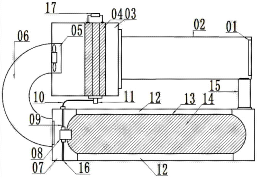
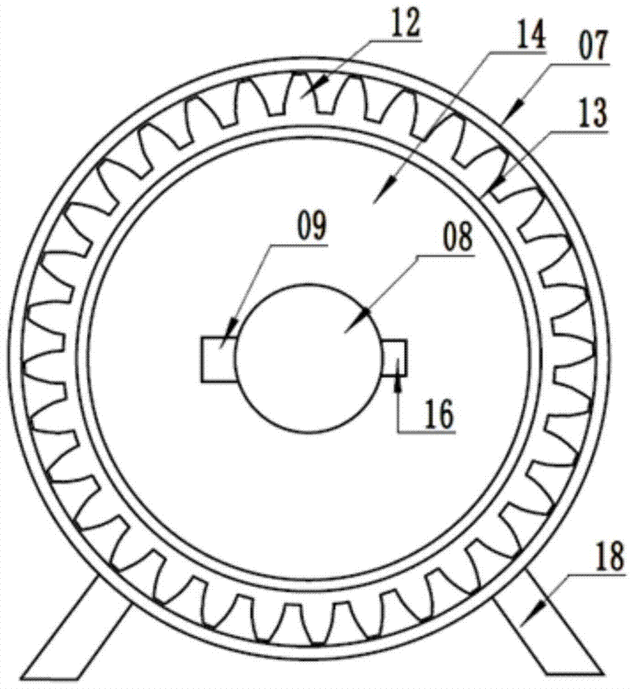
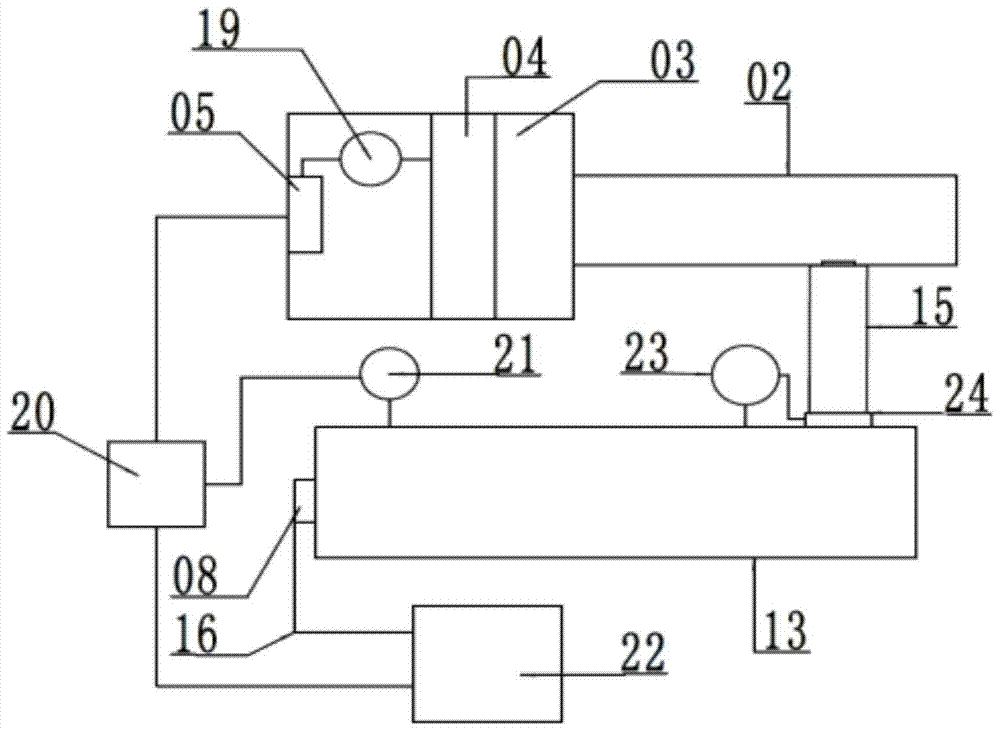
[0030] Figure 1-3 It is a metal hydride hydrogen storage and fuel cell combined system of the present invention. The system is an emergency fuel cell backup power system installed in a mobile phone base station, including a fuel cell system, a metal hydride hydrogen storage system and an electrolyzed water hydrogen production system.

[0031] The fuel cell system includes a fuel cell 3 which is a fuel cell stack 4 obtained by stacking a plurality of minimum structural units called single cells. The cathode side of the fuel cell 3 communicates with the air inlet pipe 2, and the air inlet of the air inlet pipe 2 is provided with a filter 1, which supplies the fuel cell 3 after the air is filtered, a...


PUM


Abstract

The invention belongs to the technical field of standby power source systems of mobile phone signal substations, and particularly relates to a metal hydride hydrogen storage and fuel cell combination system. The combination system comprises a fuel cell system, a metal hydride hydrogen storage system and a water electrolysis hydrogen production system. A metal hydride hydrogen storage tank is arranged in a heat exchange chamber communicated with an exhaust pipeline. When a fuel cell works, the metal hydride hydrogen storage tank heats hydrogen storage alloy powder through hot air exhausted out of the fuel cell to release hydrogen, it is guaranteed that the hydrogen storage alloy powder is located in an effective hydrogen releasing temperature area, and therefore the effective hydrogen releasing amount is made to be the maximum. After hydrogen is introduced into the heat exchange chamber and air cooled by the hydrogen storage alloy powder is fully mixed with fresh air, the air is cyclically provided for the fuel cell, and therefore the cooling performance of the fuel cell can be improved. The method is not limited to an air cooling type fuel cell system, and can be applied to a water cooling type fuel cell system.

Description

technical field [0001] The invention belongs to the technical field of backup power systems, in particular to a metal hydride hydrogen storage and fuel cell combined system. Background technique [0002] The fuel cell system used for emergency power generation of mobile phone signal base stations generally adopts proton exchange membrane fuel cells. The fuel cell body of this fuel cell system is usually fuel obtained by stacking multiple minimum structural units called single cells battery stack. A general fuel cell includes an anode that provides hydrogen and a cathode that provides oxygen, respectively. Hydrogen is converted into active hydrogen atoms in the catalyst on the surface of the electrolyte membrane on the anode side, and further releases electrons to convert hydrogen ions. The reaction is expressed as follows: [0003] h 2 →2H + +2e (Formula 1) [0004] Hydrogen ions migrate from the anode side through the electrolyte membrane to the cathode, while electrons...

Claims


Application Information

Patent Timeline
Patent Type & Authority Patents(China)
IPC IPC(8): H01M8/04014H01M8/065
CPCH01M8/04022H01M8/04074H01M2250/10Y02E60/50
Inventor 卢淼
Owner GRIMAT ENG INST CO LTD
Why Eureka
Try Eureka