High-gain three-winding cascade boost converter

A boost converter and three-winding technology, applied in the direction of conversion equipment without intermediate conversion to AC, can solve problems such as difficult to achieve high gain, achieve high voltage gain, boost voltage gain, and small voltage stress

Active Publication Date: 2016-01-13
HARBIN INST OF TECH
View PDF3 Cites 17 Cited by
  • Summary
  • Abstract
  • Description
  • Claims
  • Application Information

AI Technical Summary

Problems solved by technology

[0004] The purpose of the present invention is to solve the problem that the traditional boost converter circuit topology is difficult to achieve high gain. The present invention provides a high-gain three-winding cascaded boost converter

Method used


Image

  • High-gain three-winding cascade boost converter
  • High-gain three-winding cascade boost converter
  • High-gain three-winding cascade boost converter

Examples


Embodiment Construction

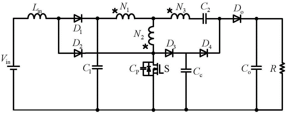
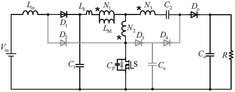
[0026] combine figure 1 To illustrate this embodiment, a high-gain three-winding cascaded boost converter described in this embodiment includes a DC voltage source, a front-stage BOOST circuit, a rear-stage three-winding coupled inductor BOOST circuit, and a clamp-boost circuit; The pre-stage BOOST circuit consists of the first and second diodes D 1 , the second diode D 2 , input inductance L in and the first output capacitor C 1 Composition; the rear-stage three-winding coupled inductor BOOST circuit consists of the first coupled inductor N 1 , the second coupled inductance N 2 , the third coupled inductor N 3 , power switch tube S, rectifier diode D o and a second output capacitor C o Composition; clamp-boost circuit consists of clamp diode D 3 , boost diode D 4 , clamp capacitor C c and boost capacitor C 2 composition.

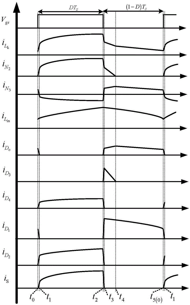
[0027] The operating principle and working process of this embodiment are as follows:

[0028] The control voltage V of the high-gain three-wi...


PUM


Abstract

The invention relates to a high-gain three-winding cascade boost converter and belongs to the field of power electronic converters. The problem that a conventional boost converter circuit cannot achieve high gain easily is solved. The converter comprises a direct-current voltage source, a preceding stage BOOST circuit, a rear stage three-winding coupling inductor BOOST circuit and a clamping-booster circuit. The preceding stage BOOST circuit is composed of a first diode D1, a second diode D2, an input inductor Lin and a first output capacitor C1. The rear stage three-winding coupling inductor BOOST circuit is composed of a first coupling inductor N1, a second coupling inductor N2, a third coupling inductor N3, a power switch tube S, a rectifier diode Do and a second output capacitor Co. The clamping-booster circuit is composed of a clamping diode D3, a booster diode D4, a clamping capacitor Cc and a boost capacitor C2. When the turn ratio of a coupling inductive winding is smaller, the voltage gain is higher. Due to the cascade characteristics, the high voltage gain can be achieved through small duty cycle, and the voltage stress of the power switch tube is small. The high-gain three-winding cascade boost converter is mostly applied to a distributed power supply system.

Description

technical field [0001] The invention belongs to the field of power electronic converters. Background technique [0002] The boost converter is widely used in the front-end converter of the distributed power system to realize boost or power factor correction. The traditional boost converter circuit topology is a Boost circuit. In theory, the voltage gain of the Boost circuit increases with the increase of the duty cycle. However, considering the parasitic equivalent series impedance in the actual circuit, the actual gain of the Boost circuit is not always It becomes larger as the duty cycle increases, so its boost capability is very limited, and it is not suitable for high-gain DC power conversion applications. [0003] The cascaded boost converter can further expand the gain, but the stress on the device is large, and it is still difficult to achieve high gain due to the influence of parasitic parameters, and it is only controlled by a single duty cycle. Contents of the i...

Claims


Application Information

Patent Timeline
Patent Type & Authority Applications(China)
IPC IPC(8): H02M3/07
Inventor 刘洪臣李飞纪玉亮范国磊沈志芳张力彬李熙
Owner HARBIN INST OF TECH
Why Eureka
Try Eureka