Lock catch type rigid and plastic compound bulging die for hydraulically-controlled T-branch pipe

A compound and bulging technology, applied in the direction of pushing out equipment, etc., can solve the problems of low service life of the punch, complex mold structure, and too small size of the tube blank, and achieve the effect of reducing the thrust

Inactive Publication Date: 2016-01-20
XINCHANG HANGDA MACHINERY MFG
View PDF7 Cites 0 Cited by
  • Summary
  • Abstract
  • Description
  • Claims
  • Application Information

AI Technical Summary

Problems solved by technology

[0009] Compared with the liquid medium extrusion bulging method, although the plastic medium separation punch extrusion bulging method is more complicated, it avoids the expensive hydraulic pressure boosting system, so it has less equipment investment, high productivity and good forming effect. Good advantages, but it also has a low service life of the punch, a complex mold structure, and cannot be applied to occasions where the size of the tube blank is too small

Method used


Image

  • Lock catch type rigid and plastic compound bulging die for hydraulically-controlled T-branch pipe
  • Lock catch type rigid and plastic compound bulging die for hydraulically-controlled T-branch pipe
  • Lock catch type rigid and plastic compound bulging die for hydraulically-controlled T-branch pipe

Examples


Embodiment Construction

[0031] The present invention will be further described below in conjunction with the accompanying drawings and specific embodiments, so that those skilled in the art can better understand the present invention and implement it, but the examples given are not intended to limit the present invention.

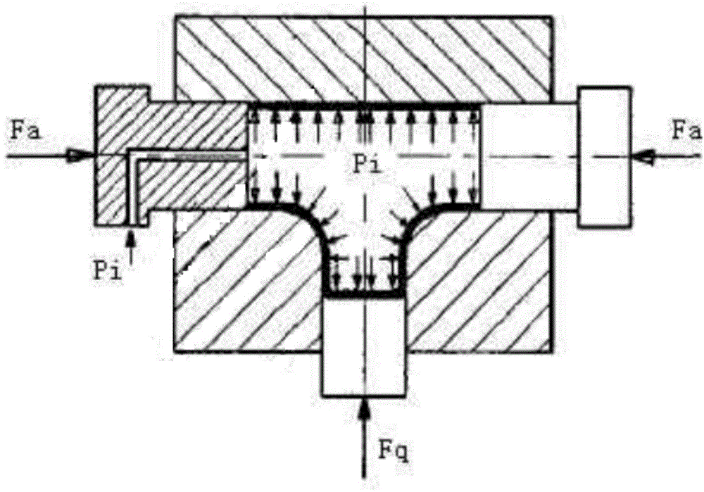
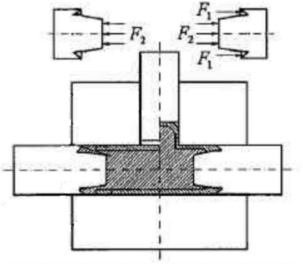
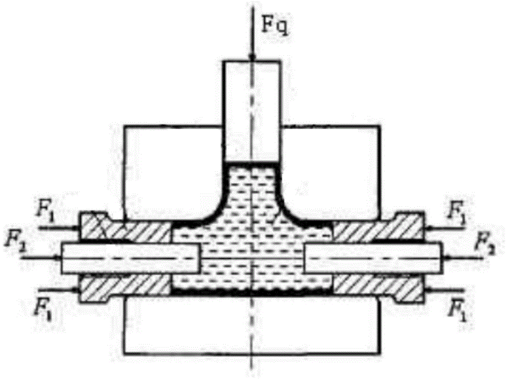
[0032] Such as Figure 4 As shown, it is a structural schematic diagram of a three-way pipe rigid-plastic composite bulging device adopting a hydraulically controlled three-way pipe lock type rigid-plastic composite bulging mold of the present invention. The three-way pipe rigid-plastic composite bulging device includes the hydraulically controlled three-way pipe lock type rigid-plastic composite bulging mold and the thrust device of this embodiment. The liquid-controlled three-way pipe lock type rigid-plastic composite bulging mold of this embodiment includes an upper half-mold 1 and a lower half-mold 2, and a circular tubular forming mold is arranged between the upper half-mold ...


PUM


Abstract

The invention discloses a lock catch type rigid and plastic compound bulging die for a hydraulically-controlled T-branch pipe. The lock catch type rigid and plastic compound bulging die comprises an upper half die and a lower half die. A forming cavity is formed between the upper half die and the lower half die. Bulging squeezing punches are mounted at the two ends of the forming cavity respectively. The lower half die is provided with a branch pipe forming cavity, and a balance punch is mounted in the branch pipe forming cavity. A rigid bulging inner die is arranged between the two bulging squeezing punches and comprises pushing rods located at two ends respectively. A forming inner die block is arranged between the two pushing rods. The forming inner die block is connected with the two pushing rods through double-hinge connection rods. The opposite ends of the pushing rods are provided with connection grooves facing the opening of the branch pipe forming cavity. Limiting structures used for preventing the axes of the two double-hinge connection rods from coinciding are arranged in the connection grooves. The axes of the pushing rods are parallel to the axis of the forming cavity. The pushing rods are mounted in the corresponding bulging squeezing punches in a sliding fit mode respectively. Bulging liquid inlets and bulging liquid outlets are formed in the bulging squeezing punches. One pushing rod is provided with a lock catch type quick detaching connection structure.

Description

technical field [0001] The invention belongs to the technical field of non-cutting processing of pipes, and in particular relates to a liquid-controlled three-way pipe lock type rigid-plastic composite bulging mold. Background technique [0002] There are many types of pipe bulging, mainly divided into two types: rigid bulging and soft mold bulging. Rigid punch bulging is only suitable for bulging of axisymmetric bulging parts that do not require high shape and dimensional accuracy. When liquid, gas or elastomer is used as the pressure transmission medium for bulging, it is commonly called soft mold bulging. The liquid can be oil, emulsion or water, and the elastomer usually adopts polyurethane rubber or natural rubber. Due to its unique characteristics of being easy to be solid or liquid, and recyclable and reusable, paraffin wax is also used as a bulging pressure transmission medium, and has achieved good technical results in production. Therefore, according to the diff...

Claims


Application Information

Patent Timeline
IPC IPC(8): B21D26/047B21D26/037B21D45/04
Inventor 刘胜利
Owner XINCHANG HANGDA MACHINERY MFG
Why Eureka
Try Eureka