Three-turn angle head applied to wind tunnel test

A Wind Tunnel Test, Cornering Technology

Inactive Publication Date: 2016-01-20
LOW SPEED AERODYNAMIC INST OF CHINESE AERODYNAMIC RES & DEV CENT
View PDF5 Cites 8 Cited by
  • Summary
  • Abstract
  • Description
  • Claims
  • Application Information

AI Technical Summary

Problems solved by technology

[0003] The purpose of the present invention is to provide an angular displacement component on the basis that the X-direction, Y-direction and Z-direction linear displacement components of the existing CTS system meet the continuous use conditions. Rolling γ rotation in three directions, while the load is lifted, it also solves the problems of the existing three-corner head cable exposure, poor shape rectification performance, and relatively large wind tunnel obstruction.

Method used


Image

  • Three-turn angle head applied to wind tunnel test
  • Three-turn angle head applied to wind tunnel test
  • Three-turn angle head applied to wind tunnel test

Examples


Embodiment Construction

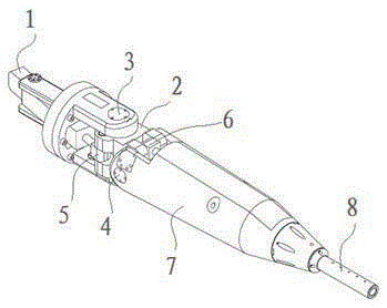
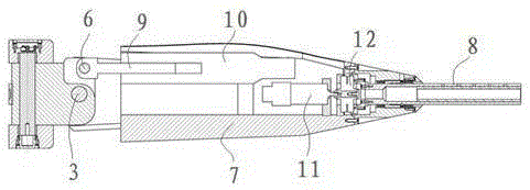
[0026] Such as figure 1 , figure 2 As shown, the three-corner head of the present invention includes a side-slip mechanism, a pitch mechanism and a roll mechanism in sequence from the rear end to the front end, and the side-slip mechanism and the pitch mechanism are arranged in series. There are two sides symmetrically arranged on the seat along the axis for connecting the shaft fork. The shaft fork and the side are connected through the longitudinal main bearing. The electric cylinder push rod shaft on the side sliding electric cylinder is connected to the shaft fork, and the electric cylinder push rod and the shaft fork are connected through a longitudinal connection shaft; The cylinder push rod shaft is connected to the shaft fork, and the electric cylinder push rod shaft and the shaft fork are connected through a transverse connecting shaft; the rolling mechanism includes a motor, a harmonic gear reducer and a strut connected with the reducer. The support rod is a hollo...


PUM


Abstract

The invention discloses a three-turn angle head applied to a wind tunnel test. The three-turn angle head sequentially comprises a sideslip mechanism, a pitching mechanism and a rolling mechanism from a rear end to a front end of the three-turn angle head. The sideslip mechanism and the pitching mechanism are connected in series. The three-turn angle head belongs to a large torque mechanical arm and can support a machine-launching model for changing in three angle directions. The movement range in a pitching direction is + / - 45 DEG, the loading capacity is 300Nm, the movement range in a sideslip direction is + / - 45 DEG, the loading capacitor is 300Nm, the movement range in a rolling direction is + / - 180 DEG, and the loading capacity is 23Nm. The invention makes innovation in the driving mode of a wind tunnel three-turn angle head, and greatly improves the captive trajectory testing capability of the wind tunnel.

Description

technical field [0001] The invention relates to the field of wind tunnel tests, in particular to a three-swivel head used in wind tunnel tests, which is used in low-speed wind tunnel capture track tests, flow field calibration tests and wake field measurement tests. Background technique [0002] The capture trajectory test is a common special wind tunnel test, which is used to simulate the flight trajectory of external objects such as aircraft missiles after they are dropped. Due to the influence of mission requirements in the 1980s (mainly carrying bombs on the carrier aircraft and small aerodynamic load) and the limitation of electromechanical technology, the existing capture trajectory device of the FL-12 wind tunnel has a relatively small design load, especially in the insufficient carrying capacity of the α mechanism. It is required that the weight of the test model cannot exceed 2kg, and the pitching moment must be less than 100Nm. However, with the increase of test t...

Claims


Application Information

Patent Timeline
Patent Type & Authority Applications(China)
IPC IPC(8): G01M9/00G05D3/12
Inventor 魏然孙传宝车兵辉刘志涛倪章松李睿吴海瀛张鹏谢琦冯国涛金启刚蒋科林姜裕标孙海生
Owner LOW SPEED AERODYNAMIC INST OF CHINESE AERODYNAMIC RES & DEV CENT
Why Eureka
Try Eureka