Light field imaging and printing device and thin film with three-dimensional floating images

A printing device and light field imaging technology, applied in optics, optical components, instruments, etc., can solve the problems of weak 3D dynamic sense and inability to realize spatial multiplexing, and achieve the effect of enriching printing modes

Active Publication Date: 2016-01-20
SVG TECH GRP CO LTD +1
View PDF8 Cites 30 Cited by
  • Summary
  • Abstract
  • Description
  • Claims
  • Application Information

AI Technical Summary

Problems solved by technology

As described in the CN200880106663.4 patent, it is a space coordinate x-y-z variable system, and the direction angle variable θ is a constant, so the system can obtain 3D depth-of-field images, but cannot realize the space multiplexing function, and due to the reasons of the previous analysis, the 3D dynamic sense is weak

Method used


Image

  • Light field imaging and printing device and thin film with three-dimensional floating images
  • Light field imaging and printing device and thin film with three-dimensional floating images
  • Light field imaging and printing device and thin film with three-dimensional floating images

Examples


Embodiment approach 1

[0071] exist Figure 6 In the light field imaging printing device shown, when printing, the cylindrical lens 4 is fixed to a certain orientation angle, and the computer controls the scanning galvanometer system 3 to keep the laser scanning on the circular arc surface of the cylindrical lens, and obtain the result through the converging lens group 6 The voxel light field is a fan-shaped surface with a fixed orientation angle, and is recorded by the microlens recording material 1 . According to the input 3D model data, the x-y-z platform where the microlens recording material 1 is located is controlled, and the light field recording of the 3D object is realized by horizontal layer-by-layer printing. Since the light field of all voxels of this 3D object is a fan-shaped area with the same orientation angle, the object can only be observed in the collection plane with this orientation angle during reproduction. When the observer changes continuously in this orientation plane Dynam...

Embodiment approach 2

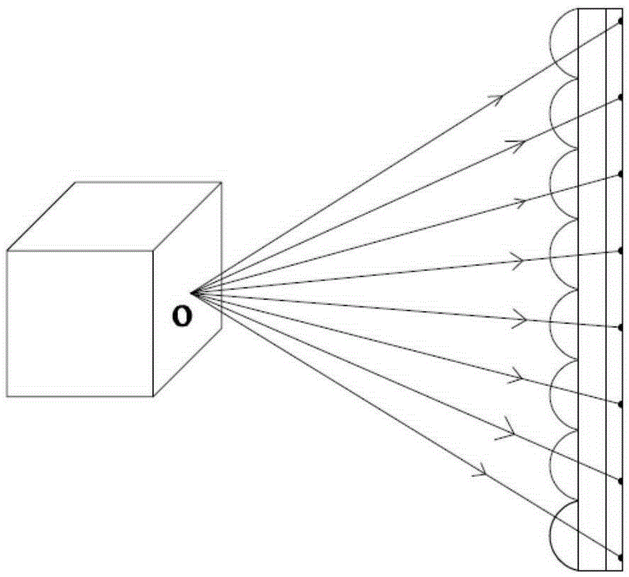
[0073] In Embodiment 1, the voxel light field can be expressed as L1(x, y, z). After completing the 3D light field imaging and printing, rotate the cylindrical lens 4 and repeat the above printing process to input another 3D object light field data L2(x, y, z), when the cylindrical lens 4 is rotated to different orientation angles, the light field data Ln(x, y, z) of different 3D objects are sequentially input. When reproducing, the principle is as described in Embodiment 1. The observer can only observe different 3D printed objects sequentially within the selected orientation angle fan-shaped assembly plane, such as Figure 10 As shown, a cubic model can be observed when at the orientation angle position, and a spherical model can be seen again when the recording material is rotated to the orientation angle. The 3D reproduction with such viewing angle characteristics can allow multiple people to observe different object information from different directions, realizing the mul...

Embodiment approach 3

[0075] As a special example of Embodiment 2, the rotation of the cylindrical lens 4 makes the orientation angle change continuously instead of having a discrete value. Here the rotation frequency of the cylindrical lens 4 should be much lower than the scanning frequency of the scanning galvanometer system 3, to ensure that the scanning galvanometer system 3 can still move the cylindrical lens 4 when the rotation angle is lower than 1 milliarc (ie 1 mrad). At least one complete scanning period is completed on the arc surface of the lens 4 . Assuming that the scanning frequency of the scanning galvanometer system 3 is T1, and the rotation frequency of the cylindrical lens 4 is T2, according to the above conditions, it should be ensured that the time for the cylindrical lens 4 to rotate 1mrad is not less than 1 / T1, so that the relationship T2≤ T1 / (2000π), such as T1=200000Hz, after calculation, the rotation frequency of the cylindrical lens 4 should not be greater than 31Hz. If ...


PUM


Abstract

The invention provides a light field imaging and printing device and a micro lens thin film with three-dimensional floating images, wherein the thin film is prepared by the light field imaging and printing device. The scanning operation on a lens surface is conducted by a scanning galvanometer system, and four-dimensional light field data can be printed in combination with the variation of space three-dimensional coordinates. The light field imaging and printing device comprises a light source, a scanning galvanometer system, a lens, a diffuser, a converging lens assembly and a micro lens recording material. Light rays sequentially pass through the scanning galvanometer system, the lens, the diffuser and the converging lens assembly, and then instantaneous and dynamic focus spots are outputted. In this way, a volumetric-pixel type radiation light field is obtained. After that, the information of the instantaneous volumetric-pixel type radiation light field is recorded by the micro lens recording material. By means of the device and the thin film, more realistic three-dimensional dynamic images can be formed. Through controlling different variable values, floating images of multiple different characteristics are formed. Therefore, the multi-view imaging effect of varying images can be realized.

Description

technical field [0001] The invention relates to the field of light field imaging, in particular to a light field imaging printing device and a film with three-dimensional floating images. Background technique [0002] The real three-dimensional object can be observed by people because the object emits light energy into the space. The object can be regarded as a collection of many point light sources that emit light, and each point light source is called a voxel of the object. When people observe a three-dimensional object, they actually obtain the spatial position information of each voxel of the object and the direction information of the light emitted by each voxel. Based on the above principles, the light field imaging theory believes that to express a three-dimensional object information on a two-dimensional plane, at least four independent variables are required, namely the three-dimensional coordinate variable x-y-z and the direction variable θ, and the light field is ...

Claims


Application Information

Patent Timeline
Patent Type & Authority Applications(China)
IPC IPC(8): G02B27/22G02B26/10
CPCG02B26/10G02B30/27
Inventor 范广飞魏国军陈林森卢国周洋
Owner SVG TECH GRP CO LTD
Why Eureka
Try Eureka