Backboard and curved-surface display device

A curved surface display device and backplane technology, which is applied to identification devices, instruments, etc., can solve the problems of high production cost, unstable surface curvature, and high cost of curved surface molds, so as to prevent springback deformation, reduce production difficulty, and low production cost Effect

Inactive Publication Date: 2016-01-20
BOE TECH GRP CO LTD +1
View PDF10 Cites 4 Cited by
  • Summary
  • Abstract
  • Description
  • Claims
  • Application Information

AI Technical Summary

Problems solved by technology

Since the bottom plate of the back plate 02 is a curved surface structure, when the back plate is made by the stamping method, there will be stress inside the formed curved surface structure, which will easily cause the bottom surface of the back plate 02 to rebound and deform, thus causing the curvature of the curved surface to be unstable; When the die-casting method is used to make the back plate, the curved surface structure is usually formed by die-casting, and the curved surface mold is usually used. The cost of the curved surface mold is high and the service life is short, thus increasing the production cost of the back plate 02
Furthermore, in order to avoid the instability of the curvature of the bottom plate when the back plate is stamped and formed, a hub frame can be used for fixed support, but the manufacturing process of the hub frame is complicated and the production cost is high, which increases the difficulty and difficulty of making the back plate 02. cost

Method used


Image

  • Backboard and curved-surface display device
  • Backboard and curved-surface display device
  • Backboard and curved-surface display device

Examples


Embodiment 1

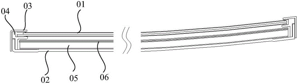
[0040] Embodiment 1: a side-in LED backlight curved surface display device. see Figure 4 , the side wall of the backplane 100 is provided with a light bar (not shown in the figure), and the light guide plate 6 is arranged on the bottom plate 1 of the backplane 100, the lower surface of the light guide plate 6 is a plane, and the upper surface of the light guide plate 6 is a curved surface , the upper surface of the light guide plate 6 is attached with an optical film group 7 , and the curvature of the upper surface of the light guide plate 6 is the same as that of the display panel 5 . In the existing technology, such as figure 1 with figure 2 As shown, the light guide plate 05 is an arc-shaped sheet-like structure with internal stress, so it is easy to deform during high-temperature and high-humidity tests. Figure 4 In the shown embodiment, the lower surface of the light guide plate 6 has a flat structure, which has good structural stability and small internal stress, s...

Embodiment 2

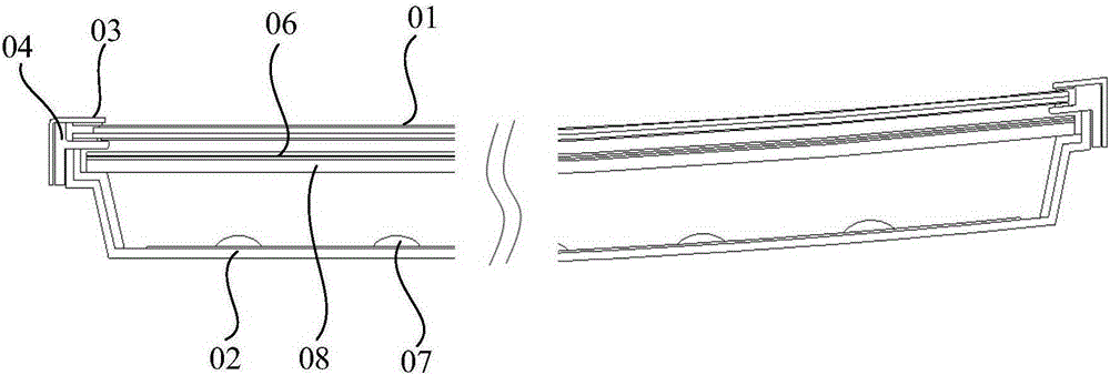
[0043] Embodiment 2: a direct-lit LED backlight curved surface display device. see Figure 5 The bottom of the backplane 100 is provided with a dot-matrix LED light source 8, and an optical cavity is provided directly above the dot-matrix LED light source. The sheet group 7 , the diffusion plate 9 and the optical film group 7 are all curved structures, and the curvatures of the diffusion plate 9 and the optical film group 7 are the same as those of the display panel 5 . Therefore, the backplane structure of the present invention can be applied to a direct-lit LED backlight curved display device, so that the display panel 5 can form a curved surface for curved display.


PUM

PropertyMeasurementUnit
Thicknessaaaaaaaaaa

Abstract

The embodiment of the invention provides a backboard and a curved-surface display device, relating to the technical field of display devices, and aiming to solve the problems that a backboard structure in the prior art easily generates rebound deformation and is high in processing cost. The backboard comprises a base plate and a side wall surrounding the edge of the base plate for a circle, wherein the base plate is a flat plate, and the upper edge of the side wall forms a curved-surface box structure used for limiting the curvature of a display panel in the curved-surface display device. The backboard can be used in the curved-surface display device.

Description

technical field [0001] The invention relates to the technical field of display devices, in particular to a backplane and a curved display device. Background technique [0002] With the development of technology, the structure of the display device can no longer be satisfied with the traditional planar structure, and a curved surface structure has begun to appear to meet the requirements of ergonomic design and improve the visual and tactile comfort of users. The composition structure of the display device with a flat structure is the same, and the display device with a curved surface includes a display panel, a backplane, a front frame, a plastic frame and a backlight, etc., wherein the backplane is a supporting part of the display panel, and its structural stability affects the display. Assembly of device assemblies. [0003] In the prior art, the cross-sectional structure of a side-in LED (Light emitting diode, Light Emitting Diode) backlight curved surface display device...

Claims


Application Information

Patent Timeline
IPC IPC(8): G09F9/00
CPCG09F9/00
Inventor 韩锐
Owner BOE TECH GRP CO LTD
Why Eureka
Try Eureka