A kind of electrochemical battery and preparation method thereof
An electrochemical and battery technology, applied in the field of electrochemical batteries, can solve the problems of poor performance and vulnerability to damage of flexible batteries, and achieve the effects of reduced energy density, high safety performance, and reduced process
- Summary
- Abstract
- Description
- Claims
- Application Information
AI Technical Summary
Problems solved by technology
Method used
Image
Examples
Embodiment 1
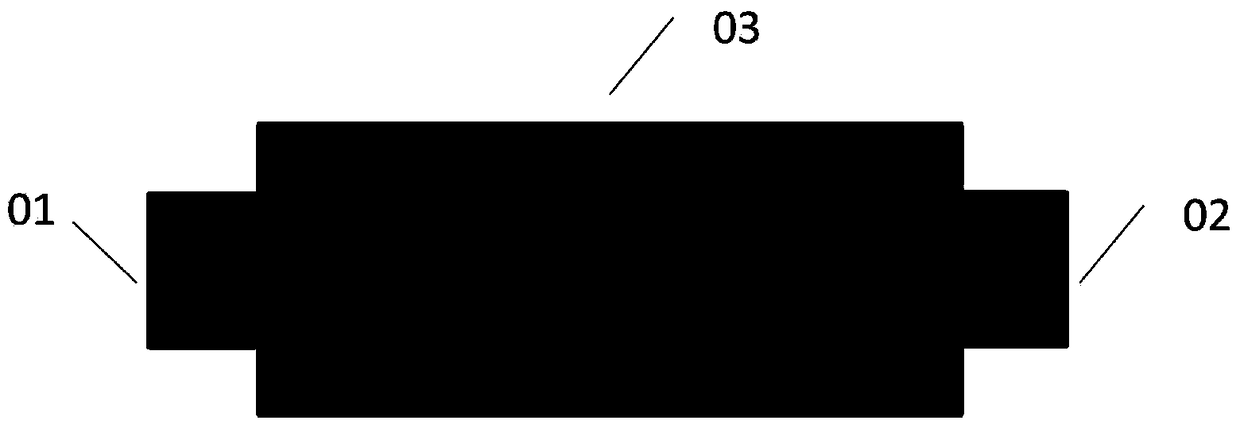
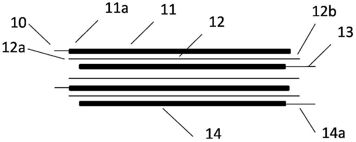
[0038] figure 1 It is a schematic top view of one structure of the electrochemical cell of the present invention: the negative pole tab 01 and the positive pole tab 02 are distributed on the two opposite sides of the cell body 03, that is, the positive pole tab 02 and the negative pole tab 01 are not separated from the cell body 03 leads out from the same side. figure 2 It is a schematic cross-sectional view of the main body of the electrochemical cell of the present invention. It can be obtained from the figure that the negative electrode collector 10 is coated with a negative electrode coating to obtain a negative electrode sheet 11, and the positive electrode collector 13 is coated with a positive electrode coating to obtain a positive electrode sheet 14. 12 is located between the negative electrode sheet 10 and the positive electrode sheet 14; on the left side of the schematic diagram are the negative electrode sheet extension structure 11a and the separator extension str...
Embodiment 2
[0046] The difference from Example 1 is that it includes the following steps:
[0047] Electrode sheet preparation: use lithium cobaltate as the positive electrode active material, PVDF as the binder, and Super-P as the conductive agent NMP as the solvent, stir evenly, and coat it to obtain a coating area and an empty foil area along the coating direction. Coil, then cold-pressed into strips (the width of the empty foil area after stripping is 10mm), and the positive electrode sheet to be wound is obtained; graphite is used as the negative electrode active material, SBR and CMC are used as the binder, Super-P is used as the conductive agent, Water is the solvent, stirred evenly, and coated to obtain a coil material forming a coated area and an empty foil area along the coating direction, and then cold-pressed into strips (the width of the empty foil area after striping is 50 mm), and the coil to be wound is obtained. Negative plate.
[0048] Bare cell assembly: Wind the above...
Embodiment 3
[0053] The difference from Example 1 is that it includes the following steps:
[0054] Electrode sheet preparation: use lithium cobaltate as the positive electrode active material, PVDF as the binder, and Super-P as the conductive agent NMP as the solvent, stir evenly, and coat it to obtain a coating area and an empty foil area along the coating direction. Coil material, then cold-pressed into strips (the width of the empty foil area after stripping is 2mm), and then a layer of ceramic layer with a thickness hc of 1 μm and a width d1 of 2 mm is coated on the head of the positive electrode coating layer as an anti-burr short circuit Treat the layer to obtain the positive electrode sheet to be wound; use graphite as the negative electrode active material, SBR and CMC as the binder, Super-P as the conductive agent, and water as the solvent to stir evenly, and then apply it to form a coating along the coating direction. The roll material in the application area and the empty foil ...
PUM
| Property | Measurement | Unit |
|---|---|---|
| thickness | aaaaa | aaaaa |
| thickness | aaaaa | aaaaa |
| pore size | aaaaa | aaaaa |
Abstract
Description
Claims
Application Information
 - R&D
- Intellectual Property
- Life Sciences
- Materials
- Tech Scout
- Unparalleled Data Quality
- Higher Quality Content
- 60% Fewer Hallucinations
Browse by: Latest US Patents, China's latest patents, Technical Efficacy Thesaurus, Application Domain, Technology Topic, Popular Technical Reports.
© 2025 PatSnap. All rights reserved.Legal|Privacy policy|Modern Slavery Act Transparency Statement|Sitemap|About US| Contact US: help@patsnap.com


