Eureka AIR delivers breakthrough ideas for toughest innovation challenges, trusted by R&D personnel around the world.

Enhanced logic conversion circuit device

A logic conversion and circuit device technology, applied in the direction of logic circuit connection/interface layout, etc., can solve problems that affect the normal operation of equipment, difficulty in removal, and impact

Inactive Publication Date: 2016-01-20
江苏万邦微电子有限公司
View PDF10 Cites 0 Cited by
  • Summary
  • Abstract
  • Description
  • Claims
  • Application Information

AI Technical Summary

Problems solved by technology

With the introduction of logic conversion measures, the number of components will inevitably increase. In addition, with the improvement of integration, the miniaturization trend of logic conversion circuits is also getting higher and higher, which will inevitably increase the temperature of logic conversion circuits. High, which affects the normal operation of the equipment, so it is necessary to keep the air around the logic conversion circuit flowing, and take away the heat of the logic conversion circuit from time to time, but because the air often contains a large number of impurity particles, these impurity particles tend to adhere to In the logic conversion circuit, this will also have a bad impact on the performance of the logic conversion circuit
In addition, the existing devices for removing impurity particles are often difficult to remove when removing impurity particles

Method used


Image

  • Enhanced logic conversion circuit device
  • Enhanced logic conversion circuit device
  • Enhanced logic conversion circuit device

Examples


Embodiment Construction

[0013] Below in conjunction with accompanying drawing, content of the invention will be further described:

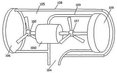
[0014] refer to figure 1 , figure 2 , image 3 As shown, the enhanced logic conversion circuit device includes a logic conversion circuit, and the logic conversion circuit is placed in the impurity removal device. In addition, the impurity removal device includes a first hollow housing 108 and a first hollow housing The second hollow cover 109 in the body 108, the motor 1010 is installed in the first hollow cover 108, the first air intake fan 102 is installed on the motor shaft of the motor 1010, the first hollow One end of the cover body 108 is an air inlet, the other end of the first hollow cover body 108 is an outlet for particulate impurities, and the outlet for particulate impurities is covered with a cover 106 with a mesh. One end of the second hollow cover body 109 is an air inlet, and the air inlet position of the second hollow cover body 109 is surrounded b...


PUM


Abstract

The invention relates to an enhanced logic conversion circuit device. A circuit port structure of a logic conversion circuit is in double-loop protection; simultaneously, an ESD (Electronic Static Discharge) input layer is additionally arranged at an NMOS (N-channel Metal Oxide Semiconductor) tube part of the circuit; a particle impurity channel is formed between a first hollow cover body and a second hollow cover body; a clean airflow channel is formed between a reverse osmosis membrane of the first hollow cover body and an air outlet; and the head face of the reverse osmosis membrane is an arched surface or a reduced surface capable of separating particle impurities from the reverse osmosis membrane under driving of external force. By means of such a structure, the disadvantages that bad effects are brought about to performances of the logic conversion circuit due to the fact that impurity particles are often attached in the logic conversion circuit, and the removing difficulty of the current impurity particle removing device is often high while removing the impurity particles in the prior art can be avoided; the ESD capability of the circuit port is also increased; and the ESD capability of the circuit is also increased by additionally arranging a protective diode between the circuit and a power ground.

Description

technical field [0001] The invention belongs to the technical field of conversion circuits, and in particular relates to an enhanced logic conversion circuit device. Background technique [0002] In the new generation of electronic circuit design, with the introduction of low-voltage logic, the problem of input / output logic inconsistency often occurs inside the system, which increases the complexity of system design. For example, when a 1.8V digital circuit communicates with an analog circuit operating at 3.3V, it is necessary to first solve the conversion problem of the two levels, and then a logic conversion circuit device is required. With the continuous emergence of digital ICs with different operating voltages, the necessity of logic conversion circuit devices has become more prominent. Varies depending on the transfer rate. With the introduction of logic conversion measures, the number of components will inevitably increase. In addition, with the improvement of integ...

Claims


Application Information

Patent Timeline
IPC IPC(8): H03K19/0175
Inventor 朱勤辉张林窦延军张春秋
Owner 江苏万邦微电子有限公司
Why Eureka
Eureka Blog
Learn More