Unbalanced shaft

A balance shaft and balancing technology, applied in the direction of spring/shock absorber, machine/engine, vibration suppression adjustment, etc., can solve the problems of complicated installation and cost-intensive, and achieve the effect of simple axial and/or radial fixation

Inactive Publication Date: 2016-01-27
AB SKF
View PDF2 Cites 7 Cited by
  • Summary
  • Abstract
  • Description
  • Claims
  • Application Information

AI Technical Summary

Problems solved by technology

However, this is complex to install and therefore cost-intensive

Method used


Image

  • Unbalanced shaft
  • Unbalanced shaft

Examples


Embodiment Construction

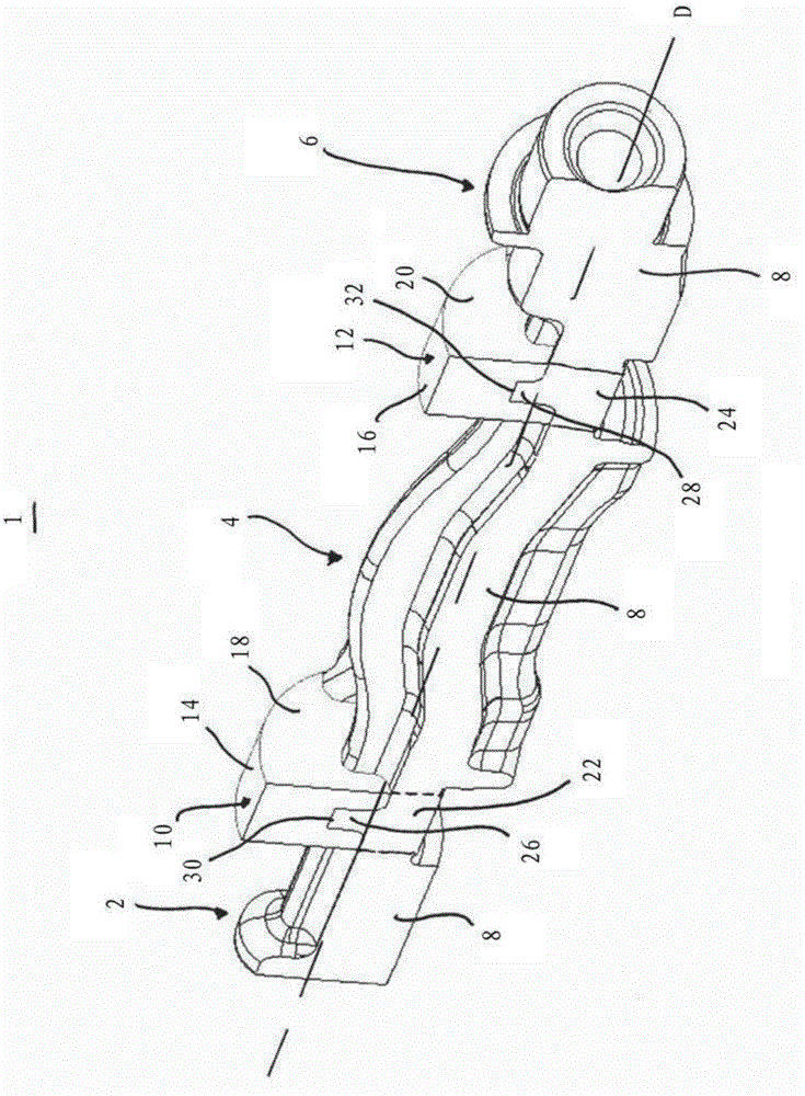
[0018] figure 1 A perspective section through an unbalanced shaft 1 is shown, which has a plurality of shaft sections 2 , 4 and 6 and is mounted rotatably along an axis of rotation D. FIG. An unbalanced mass 8 is arranged on the shaft sections 2 , 4 and 6 in each case, which ensures a center of gravity that is eccentrically formed with respect to the axis of rotation D. FIG. figure 1 It is also shown that the imbalance shaft 1 can be supported radially by means of bearing journals 10 , 12 . The bearing journals 10 , 12 thus generally serve as inner running surfaces for the rolling bodies (not shown) of rolling bearings with line contact, so that the cylindrical outer surfaces 14 , 16 of the bearing journals 10 , 12 simultaneously serve as contact surfaces for the rolling bodies. working surface. Rolling bearings with line contact are considered to be all rolling bearings of this type in which the rolling elements contact their running surfaces along a straight line. These a...


PUM


Abstract

An unbalanced shaft (1) for compensating inertial forces and / or moments of inertia for a reciprocating internal combustion engine includes at least one shaft section (2,4,6) and a bearing journal (10,12) adjacent to the at least one shaft section (2,4,6) and an unbalance mass (8) disposed on the shaft section (2,4,6). The bearing journal (10,12) is formed from at least two parts including a first solid bearing segment (18,20) and a second solid bearing segment (22,24), and a center of gravity of the shaft section (2,4,6) and the bearing journal (10,12) is eccentric to an axis of rotation (D) of the unbalanced shaft (1). The first solid bearing segment (18,20) includes a portion projecting into the second solid bearing segment and the second solid bearing segment (22,24) include a portion projecting into the first solid bearing segment such that the first and the second solid bearing segment are secured at least axially relative to each other.

Description

technical field [0001] The invention relates to an unbalanced shaft for balancing inertial forces and / or moments of inertia, in particular in reciprocating piston internal combustion engines. Background technique [0002] Unbalanced shafts are known from the prior art, such as document DE 10 2007 027 990, which have a shaft section and a bearing journal, wherein the bearing journal is designed as a part cylinder, thereby also contributing to the asymmetry of the shaft. It is also known from document DE 10 2009 035 112 that the bearing journal consists of two heavy bearing journal sections, one of which is made of metal and the other of which is made of plastic. Although such a shape of the unbalanced shaft significantly reduces the overall weight of the unbalanced shaft, the known shape of the bearing arrangement with two bearing sections has the disadvantage that the bearing sections are usually opposite to each other. Move to the ground. In contrast, if only a partial cy...

Claims


Application Information

Patent Timeline
Patent Type & Authority Applications(China)
IPC IPC(8): F16F15/26F02B75/06
CPCF16F15/267
Inventor R.鲍赫D.路德维格
Owner AB SKF
Why Eureka
Try Eureka