Composite cooling structure for wall of combustion chamber flame tube of aero-engine

An aero-engine and composite cooling technology, which is applied in the field of engineering heat and mass transfer, can solve the problems of inability to cool the airflow and increase the temperature of the cooling capacity, and achieve the effects of improved utilization, light weight, and small structural size

Inactive Publication Date: 2016-01-27
中航空天发动机研究院有限公司
View PDF11 Cites 13 Cited by
  • Summary
  • Abstract
  • Description
  • Claims
  • Application Information

AI Technical Summary

Problems solved by technology

However, the effective heat exchange area of ​​impingement cooling does not increase much, and the cooling airflow cannot be effectively heated up, and the utilization level of cooling capacity is not high.

Method used


Image

  • Composite cooling structure for wall of combustion chamber flame tube of aero-engine
  • Composite cooling structure for wall of combustion chamber flame tube of aero-engine
  • Composite cooling structure for wall of combustion chamber flame tube of aero-engine

Examples


Embodiment Construction

[0030] The present invention will be further described in detail below in conjunction with examples, but the embodiments of the present invention are not limited thereto.

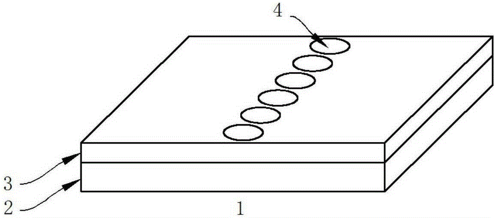
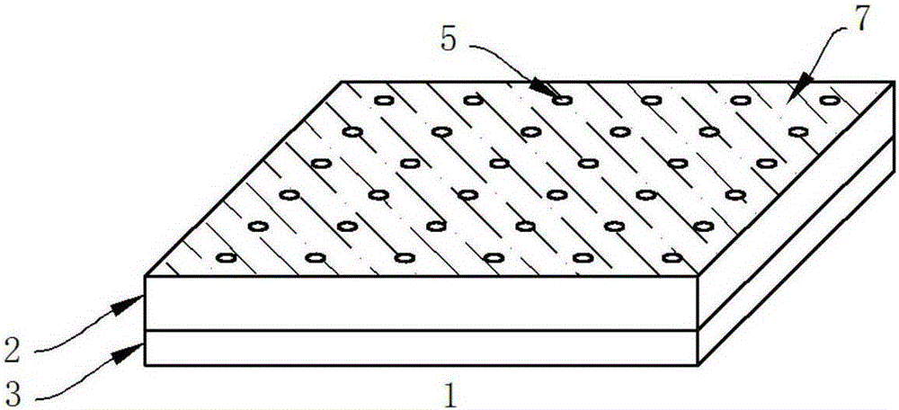
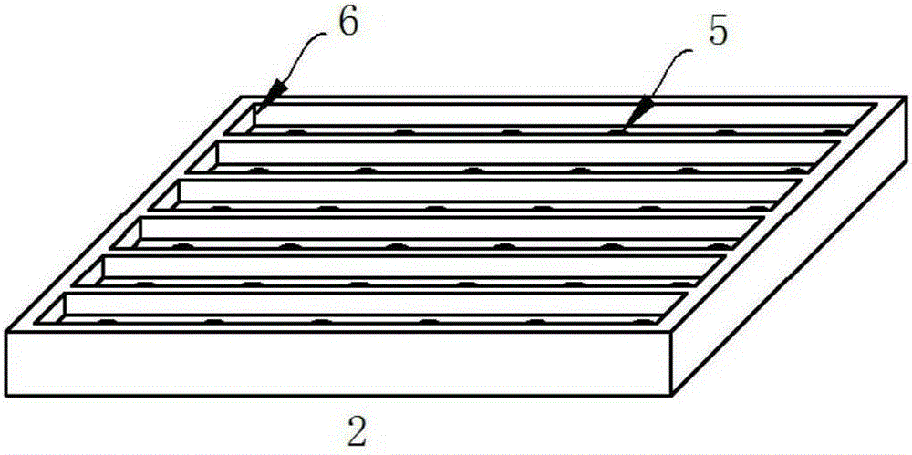
[0031] The present invention is a compound cooling structure (that is, a cooling tile 1 ) capable of effectively improving the utilization level of the cooling air of an aeroengine, which is composed of a double-layer wall surface: a cooling structure bottom plate wall surface 2 and a cooling structure cover plate wall surface 3 . The six large through holes 4 on the wall surface of the cooling structure cover plate face the center of the six micro-scale channel grooves 6 on the wall surface 2 of the cooling structure bottom plate, and the two layers of walls are integrated by welding. see figure 1 and figure 2 .

[0032] figure 1 It is a structural schematic diagram of the outer surface of the cooling structure, which is welded by the cooling structure bottom wall 2 and the cooling structure cover wall...


PUM


Abstract

The invention discloses a composite cooling structure for the wall of a combustion chamber flame tube of an aero-engine. The composite cooling structure is composed of a bottom plate wall (2) and a cover plate wall (3). The interior of the bottom plate wall (2) is cut into six parallel-connection micro-scale channel grooves (6) in the flowing direction of the flame tube, and six small air outlet through holes (5) are formed in the center line of each cut micro-scale channel groove (6). Large air inlet through holes (4) are formed in the position, corresponding to each cut micro-scale channel groove (6), of the cover plate wall (3). The bottom plate wall (2) and the cover plate wall (3) are welded into a whole, after welding is finished, bending treatment is carried out in the circumferential direction of the flame tube, and the side wall of the bottom plate wall (2) is coated with a heat barrier coating (7). According to the cooling structure, micro-scale channel cooling and diffusion hole air film cooling are combined, the micro-scale structure is fully utilized for enhancing heat transfer, and the cooling capacity of cooling air flow is achieved. The structural design and machining are simple, and the cooling structure can be achieved easily in actual machine types.

Description

technical field [0001] The invention belongs to the technical field of engineering heat and mass transfer, and in particular relates to a tile-like structure applied to composite cooling of the wall surface of a flame tube of an aeroengine combustion chamber. Background technique [0002] The combustor flame tube is the area where the aero-engine organizes combustion, and the temperature of the gas in this area is the highest. The cooling technology of the flame tube is directly related to the life and reliability of the combustion chamber, and affects the thermal efficiency of the entire engine. There are a lot of design research at home and abroad. [0003] The early combustion chamber flame tube cooling structure generally adopts a single-layer wall structure, and the overall cooling efficiency of such a structure is not high. The more advanced combustor flame tubes in the prior art mostly adopt a double-wall cooling structure, and the overall layout of the combustor fl...

Claims


Application Information

Patent Timeline
Patent Type & Authority Applications(China)
IPC IPC(8): F23R3/42
Inventor 苗辉王爱峰刘金龙
Owner 中航空天发动机研究院有限公司
Why Eureka
Try Eureka