
Radiation electron heating electron gun

An electronic heating and electron gun technology, applied in the direction of thermionic cathode, electron emission electrode/cathode, electrode assembly support/installation/spacing/insulation, etc., can solve the difficulty of cathode temperature control, increase the temperature of cathode filament assembly, and electron gun High scrap rate and other issues, to avoid high temperature contact, improve cathode electric field strength, and long life

Inactive Publication Date: 2016-01-27
HUADONG PHOTOELECTRIC TECHN INST OF ANHUI PROVINCE
View PDF3 Cites 3 Cited by
  • Summary
  • Abstract
  • Description
  • Claims
  • Application Information

AI Technical Summary

Problems solved by technology

This kind of cathode-filament assembly that realizes heat exchange by conduction has many disadvantages, such as low life due to the electron-chemical interaction between the filament and the ceramic insulating composition; When the frequency is stable, it is more difficult to control the cathode temperature; since the cathode filament assembly is composed of materials with different physical properties, it is necessary to increase (and decrease) the temperature of the cathode filament assembly steadily, so that the filament switching process lasts longer (up to 10-15min); the traditional filament assembly manufacturing process is very difficult, and the electron gun scrap rate is very high when testing or using
In addition, focusing electrodes or confinement shields are often used in the traditional electron gun structure, but the trajectory analysis data and experimental studies of the microstructure have proved that the electron beam structure with a very fine absolute size, especially the strip electron injection gun, due to the electrode near the cathode and the cathode The static disturbance brought by the combined electronic dynamic lens exceeds the disturbance caused by thermal velocity difference and space charge by as much as 10 times

Method used


Image

  • Radiation electron heating electron gun
  • Radiation electron heating electron gun
  • Radiation electron heating electron gun

Examples


Embodiment Construction

[0033] The specific embodiment of the present invention will be described in further detail by describing the embodiments below with reference to the accompanying drawings, the purpose is to help those skilled in the art to have a more complete, accurate and in-depth understanding of the concept and technical solutions of the present invention, and contribute to its implementation.

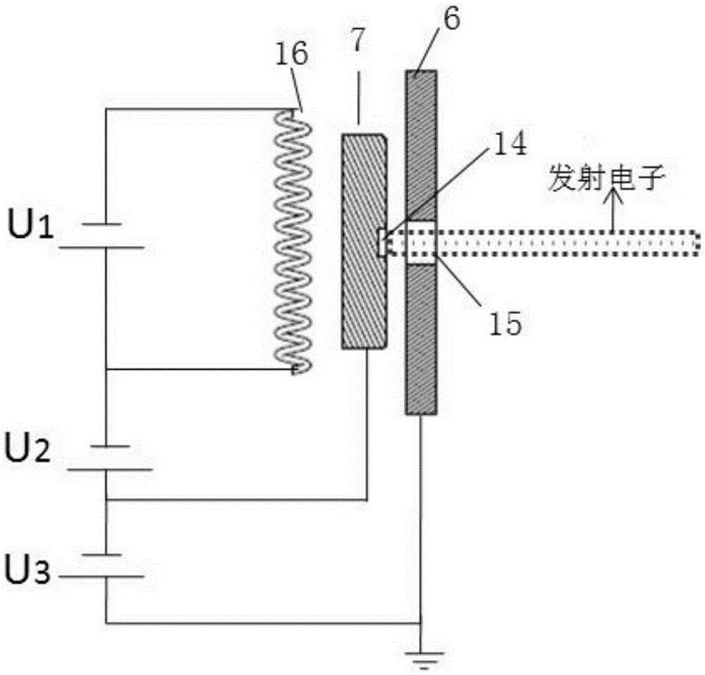
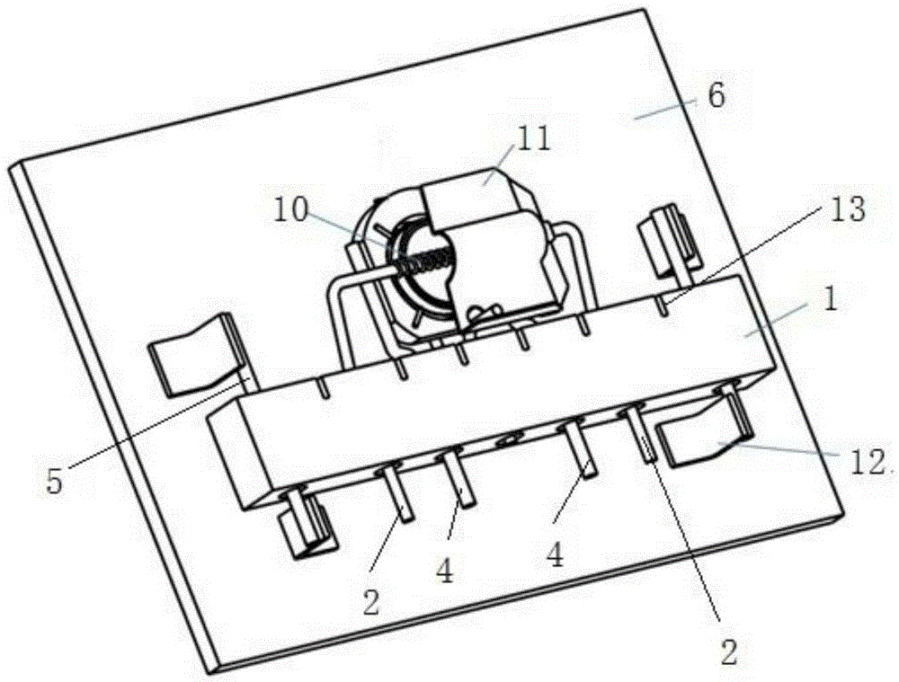
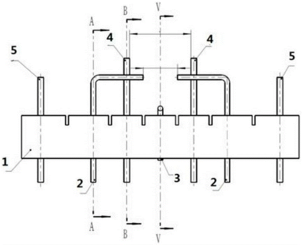
[0034] Such as Figure 1 to Figure 13 As shown, the present invention is a radiation electron heating type electron gun. The electron gun includes an insulator assembly, an anode plate 6 arranged in sequence, a cathode assembly for emitting electrons, and a filament assembly for electronically heating the cathode assembly. The anode plate is provided with a The anode hole 15 from which the electrons are emitted, the anode plate 6, the cathode assembly and the filament assembly are fixedly connected by an insulator assembly.

[0035] A device for accelerating the emitted electrons at high voltage ...


PUM


Abstract

The present invention discloses a radiation electron heating electron gun. The radiation electron heating electron gun comprises insulator components, an anode plate successively arranged, a cathode component configured to emit electrons and a filament component configured to perform electronic heating of the cathode component. The anode plate is provided with an anode hole configured to lead out emitting electrons; and the anode plate, the cathode component and the filament component are fixedly connected with each other through the insulator components. According to the invention, the electron heating mode of a cathode, with a long life, a short switch response time, a short length of an axis, a simple process and the like, is used. Moreover, a planar electrode structure is adopted to form fine electron beams, especially banding electron beams, wherein the banding electron beams may effectively avoid electron disturbance and the electron beam edge vortex layer containing few electrons and improve the quality of electrons emitted by an electron gun provided by the invention.

Description

technical field [0001] The invention belongs to the technical field of vacuum electronic devices, and in particular relates to a radiation electron heating type electron gun. Background technique [0002] The electron gun is a part of the electron optical system in the vacuum electronic device, limited by the magnetic field, forms and transmits the flying electron beam in the vacuum electron tube. In the traditional electron gun structure, the filament is buried in the cathode, and the temperature of the filament rises after being energized, and the cathode is heated by conduction. This kind of cathode-filament assembly that realizes heat exchange through conduction has many disadvantages, such as low life due to the electron-chemical interaction between the filament and the ceramic insulating composition; When the frequency is stable, it is more difficult to control the cathode temperature; since the cathode filament assembly is composed of materials with different physica...

Claims


Application Information

Patent Timeline
IPC IPC(8): H01J19/02H01J19/04H01J19/16H01J19/42
Inventor 席洪柱张建成尚吉花王鹏康董彬彬
Owner HUADONG PHOTOELECTRIC TECHN INST OF ANHUI PROVINCE
Learn More