Light source module and packaging method thereof, and lighting device using the light source module

A technology of a light source module and a packaging method, which is applied to lighting devices, components of lighting devices, light sources, etc., and can solve the problem of low luminous efficiency of light-emitting diode lamps, limited light-emitting diode irradiation area, and insufficiently wide lighting range and other problems, to achieve the effect of wide lighting range, small color temperature deviation, and reduced light attenuation

Inactive Publication Date: 2016-01-27
简汝伊
View PDF5 Cites 3 Cited by
  • Summary
  • Abstract
  • Description
  • Claims
  • Application Information

AI Technical Summary

Problems solved by technology

[0003] However, light-emitting diodes have a limited irradiation area and a certain irradiation direction. Therefore, the lighting range when applied to lamps is not wide enough, and it cannot have a full-circumferential radial lighting range like the light of traditional fluorescent lamps. In addition, with Take the white light-emitting diode lamps on the market as an example. The yellow phosphor is coated on the blue light-emitting diode. The light source energy emitted by the light-emitting diode can excite the yellow phosphor to emit a yellow fluorescence. Therefore, the light-emitting diode After the blue light emitted by the diode is mixed with the yellow fluorescent light, white light can be formed. However, most of the existing phosphors are directly coated on the light-emitting diodes and packaged together in the same chip layer, so the phosphors will be affected. When the light-emitting diode emits light, it is attenuated by the influence of heat energy, which causes the overall light-emitting diode lamp to be prone to instability and light decay, and the luminous efficiency (lm / W) of the overall light-emitting diode lamp is not high, and the color temperature The offset is also larger

Method used


Image

  • Light source module and packaging method thereof, and lighting device using the light source module
  • Light source module and packaging method thereof, and lighting device using the light source module
  • Light source module and packaging method thereof, and lighting device using the light source module

Examples


Embodiment Construction

[0051] In order to illustrate the central idea of ​​the present invention expressed in the column of the above-mentioned summary of the invention, it is expressed in specific embodiments. Various objects in the embodiments are drawn in proportions suitable for illustration and description, rather than actual components, and are described first.

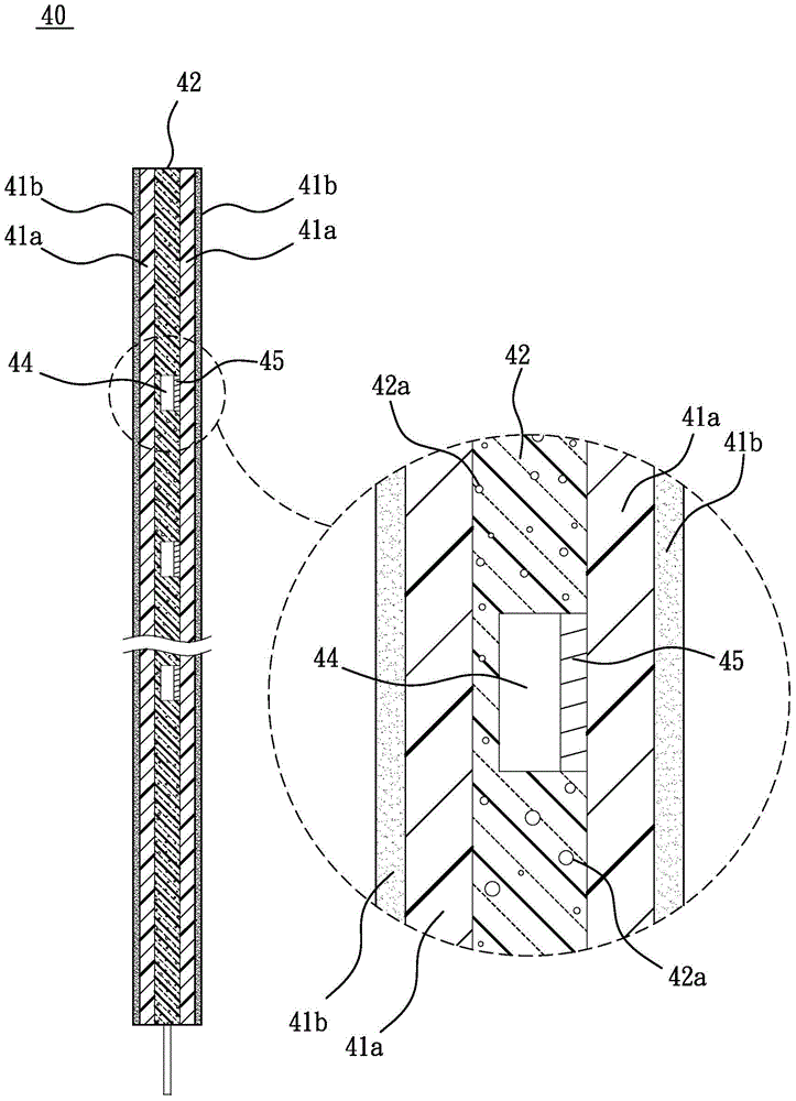
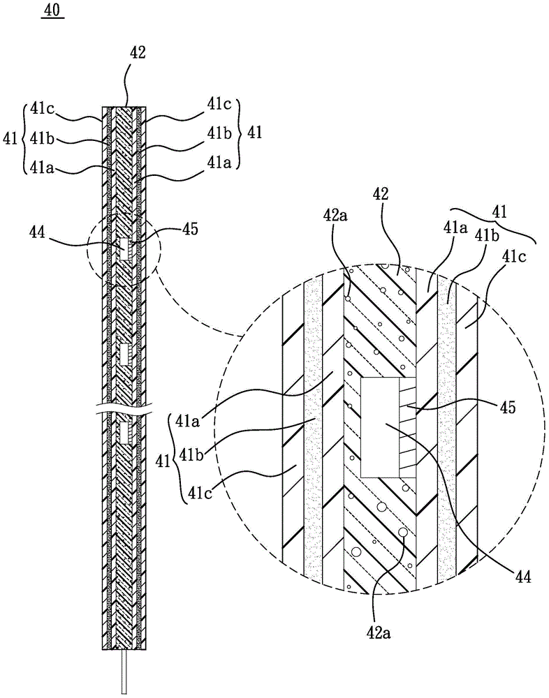
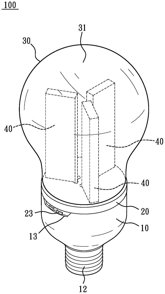
[0052] see Figure 1 to Figure 5 As shown, the present invention provides a light source module 40 and its packaging method, and a lighting device 100 using the light source module 40, wherein the packaging method of the light source module 40 of the present invention includes the following steps:

[0053](a) coating, a fluorescent glue is coated on a plane of two first transparent glass sheets 41a respectively, wherein, the length, width and thickness of each of the first transparent glass sheets 41a are 70mm, 20mm and 0.3mm respectively mm, and the fluorescent glue is composed of fluorescent powder, polymethylmethacrylate (PMMA for...


PUM


Abstract

The invention provides a light source module and a packaging method thereof, and a lighting device using the light source module. The packaging method of the light source module comprises the following steps of coating: coating fluorescent glue on two first transparent glass sheets respectively; drying: carrying out a drying step on the fluorescent glue which is coated on the two first transparent glass sheets respectively so that the two first transparent glass sheets form fluorescent glue layers respectively; packaging: packaging several light emitting diodes between the two first transparent glass sheets through an optical cement so as to form the light source module. The lighting device makes that any two adjacent light source modules form a 120-degree included angle. The lighting device possesses a peripheral light illumination area. The invention also provides the lighting device. The device comprises a lamp shell, a lamp holder, a lampshade and three light source modules, wherein the lamp shell possesses an opening; one side of the lamp shell, which is far away from the opening, possesses a conductive joint; the lamp holder is clamped in the opening; the lampshade possesses a light transmission property and is clamped in the lamp holder.

Description

technical field [0001] The invention relates to a light source module and its packaging method, and a lighting device using the light source module, so that the light decay of the light source module is reduced, and the lighting device has a full-circumference lighting range. Background technique [0002] At present, light-emitting diodes (LEDs) have many advantages such as high luminous efficiency, low power consumption and long service life, so that light-emitting diodes are currently widely used in various lighting fixtures, while the old traditional fluorescent lamps That is, it is gradually replaced by light-emitting diode lamps. [0003] However, light-emitting diodes have a limited irradiation area and a certain irradiation direction. Therefore, the lighting range when applied to lamps is not wide enough, and it cannot have a full-circumferential radial lighting range like the light of traditional fluorescent lamps. In addition, with Take the white light-emitting dio...

Claims


Application Information

Patent Timeline
Patent Type & Authority Applications(China)
IPC IPC(8): H01L25/075H01L33/48H01L33/50H01L33/54F21S2/00F21V17/16F21V19/00F21Y101/02
Inventor 简汝伊
Owner 简汝伊
Why Eureka
Try Eureka