
Tubing string rotation device

A technology of rotating device and tubing string, which is applied in drilling pipe, casing, production fluid, etc., can solve the problems of thinning and bursting of oil pipe, wear and tear of oil pipe, and inconspicuous structural effect, so as to improve economic efficiency and production, stop The effect of reducing the well phenomenon and prolonging the service life

Active Publication Date: 2017-08-15
徐伟国
View PDF10 Cites 0 Cited by
  • Summary
  • Abstract
  • Description
  • Claims
  • Application Information

AI Technical Summary

Problems solved by technology

[0002] During the operation of the pumping unit, due to the pressure of the sucker rod string’s own weight, the lower part is subjected to the resistance of the plunger in the pump barrel, making it bend below the neutral point, resulting in the sucker rod coupling on the sucker rod string The inner wall of the tubing has load eccentric wear at the same point on the same axial point, and it is periodic, long-term, and recurring load eccentric wear, especially at the upper part of the pump barrel 300-500 meters. Wear-through or thinning and bursting of tubing, this production accident has been common in all pumping wells for a long time, and has not been well resolved
[0003] Patent application number 2007101158436 "Anti-eccentric wear tubing string" provides a pair of friction pairs composed of inner and outer anti-wear bodies. More than two pairs of friction pairs are installed in the anti-eccentric wear tubing string. Under the action of the anti-wear body, the wear between the oil pipe and the sucker rod is eliminated. The effect of this structure is not obvious, and the reactive load and the upward liquid resistance are increased, resulting in the production accident of the sucker rod breakage, but it still cannot solve the problem between the rod and the pipe. partial wear

Method used


Image

  • Tubing string rotation device
  • Tubing string rotation device
  • Tubing string rotation device

Examples


Embodiment Construction

[0013] Embodiments of the present invention will be further described below in conjunction with the accompanying drawings.

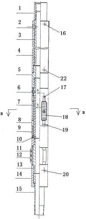
[0014] The track shaft 3 is composed of a through hole in the middle and two symmetrical 180-degree spiral track grooves 31 on the peripheral wall, such as Figure 4 , 5 , Shown in 6, there can be more than two track grooves according to the pipe diameter.

[0015] Rotation structure: the track sleeve 4 is installed outside the track shaft 3, the guide pin 2 is inserted into the track groove 31, the track shaft and the track cover are assembled into a dynamic body, and the two guide pins 2 respectively control the spiral track groove in the two track grooves 31 direction composition.

[0016] Righting resistance structure: three centering blocks 12 with springs 11 are evenly distributed on the outer periphery of the centering body 13 with a through hole in the middle and external threads at both ends, and the two ends of the centering block 12 are dyna...


PUM


Abstract

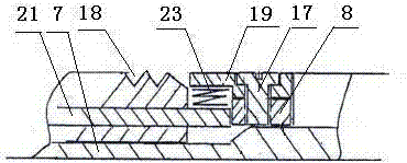
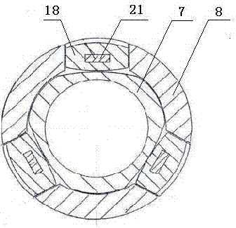
A tubing string rotation device, including rotation, anchoring, and righting resistance structure, the rotation structure is composed of a track sleeve installed outside the track shaft, and the guide pin is inserted into the track groove to play the role of rotation orientation, and the anchor structure is composed of pins at both ends of the camshaft, The positioning pin is installed on the base body, and there are evenly distributed through-hole grooves on the base body, and the through-hole slots are equipped with clamping teeth with inserts, which are formed by the movement of the clamping teeth controlled by the camshaft; It is composed of installing a centralizing block with a spring; and the rotation, anchoring and centralizing resistance structures are connected into one by a middle joint and a connecting sleeve. The pumping unit continuously reciprocates up and down, and the guide pin controls the helical track shaft to rotate in reverse and forward directions. Since the wear between the rotating oil pipe and the sucker rod will not be concentrated on the same position on the same axis, the wear will be dispersed. The inner diameter of the tubing is 180 degrees on the circumference, prolonging the service life of the tubing and sucker rods, and completely solving the long-term unresolved problem of eccentric wear between the tubing and sucker rods in pumping wells.

Description

technical field [0001] The invention relates to a special equipment in the petroleum exploration and production industry, especially a kind of equipment installed in the downhole of the pumping unit, the upper end is connected with the pump cylinder and the lower end is connected with the screen pipe, which is used to prevent the eccentric wear of the sucker rod string and the oil pipe, improve the oil pipe, oil pumping Rod life of the tubing string rotation device. Background technique [0002] During the operation of the pumping unit, due to the pressure of the sucker rod string’s own weight, the lower part is subjected to the resistance of the plunger in the pump barrel, making it bend below the neutral point, resulting in the sucker rod coupling on the sucker rod string The inner wall of the oil pipe has load eccentric wear at the same point on the same axial point, and it is periodic, long-term, and recurring load eccentric wear, especially at the upper part of the pump...

Claims


Application Information

Patent Timeline
Patent Type & Authority Patents(China)
IPC IPC(8): E21B17/00E21B17/10E21B17/042E21B43/00F04B47/00
Inventor 徐伟国
Owner 徐伟国
Learn More