Method and device for reducing oil and gas well annulus belt pressure

A technology for annular pressure and oil and gas wells, which is applied in the direction of earthwork drilling and production, wellbore/well components, etc. It can solve the problems of volume shrinkage, corrosion of annular components in the wellhead section, and rising management costs, etc., so as to slow down or reduce the sharp rise , Reduce the number of maintenance, reduce the effect of operating costs

Inactive Publication Date: 2016-02-03
BC P INC CHINA NAT PETROLEUM CORP +2
View PDF5 Cites 10 Cited by
  • Summary
  • Abstract
  • Description
  • Claims
  • Application Information

AI Technical Summary

Problems solved by technology

This approach has the following problems: 1) During the production of oil and natural gas, the pressure and temperature in the production string rise sharply. Due to the pressure and temperature effects, the pressure in each annular space rises sharply. It is difficult to judge whether this rise is the production string, Caused by leakage of packers, casings, etc., or by pressure and temperature effects; 2) A sharp rise in annular pressure may cause seal failure or rupture of production strings, packers, casings, etc.
These will lead to an increase in on-site workload and an increase in management costs; 4) Due to changes in operating pro

Method used


Image

  • Method and device for reducing oil and gas well annulus belt pressure
  • Method and device for reducing oil and gas well annulus belt pressure
  • Method and device for reducing oil and gas well annulus belt pressure

Examples


Embodiment approach 1

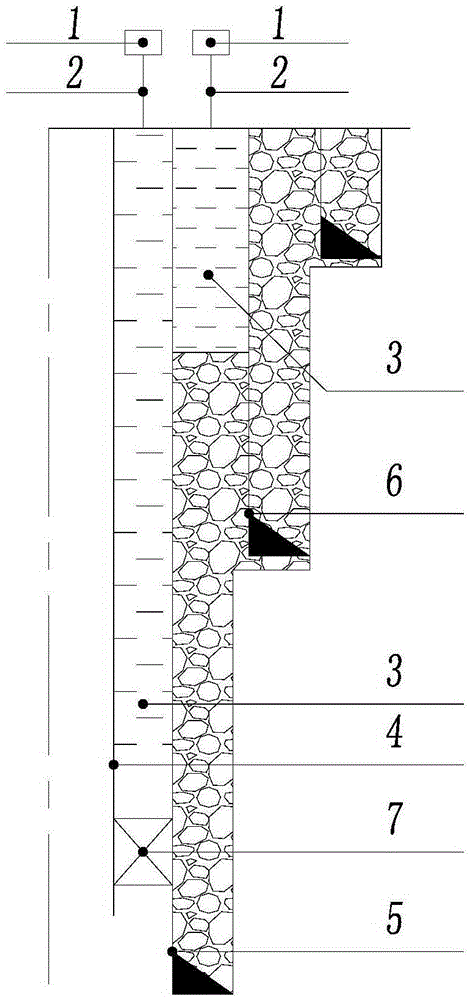
[0031] Such as figure 1 As shown, the present invention provides a kind of method for slowing down the annular pressure of oil and gas well, and it comprises the steps:

[0032] a) provide a gas storage tank 1, the gas storage tank 1 is communicated with the annulus 3 of the oil and gas well through the pipeline 2;

[0033] b) Filling the gas storage tank 1 with a predetermined volume of inert gas.

[0034] Specifically, in step a), the gas storage tank 1 is arranged at the wellhead, and communicates with the annulus 3 of the oil and gas well through a pipeline 2 . In this embodiment, the annulus 3 of the oil and gas well is completely filled with liquid.

[0035] In step b), in this embodiment, the inert gas injected into the gas storage tank 1 is nitrogen, and its volume is V. The annulus 3 of the oil and gas well is composed of an inner pipe and an outer pipe sleeved outside the inner pipe. The formed annular space, the lower part of which is sealed by the packer 7, wher...

Embodiment approach 2

[0110] Such as figure 1 As shown, the present invention also provides a device for relieving pressure in the annulus of oil and gas wells, which includes a gas storage tank 1, which communicates with the annulus 3 of the oil and gas well through a pipeline 2, and the gas storage tank 1 Filled with inert gas.

[0111] Specifically, the inner pipe can be the production string 4, the outer pipe can be the casing 5, the gas storage tank 1 is arranged at the wellhead, and it is connected to the annular space formed between the production string 4 and the casing 5 through the pipeline 2 Or, in other embodiments, the inner pipe can be the casing 5, the outer pipe can be the technical casing 6, the gas storage tank 1 is arranged at the wellhead, and it is connected to the casing 5 and the technical casing 6 through the pipeline 2 An annular space is formed between them.

[0112] The device for alleviating the pressure in the annulus of oil and gas wells needs to know the pressure of...


PUM

PropertyMeasurementUnit
Volumeaaaaaaaaaa
Diameteraaaaaaaaaa
Lengthaaaaaaaaaa

Abstract

The invention provides a method and device for reducing oil and gas well annulus belt pressure. The method for reducing the oil and gas well annulus belt pressure comprises the following steps that a gas storage tank is provided, and the gas storage tank is communicated with an oil and gas annulus through a pipeline; a preset volume of inert gas is fed into the gas storage tank. By means of the method and device for reducing the oil and gas well annulus belt pressure, sharp increase or decrease of the oil and gas well annulus pressure can be reduced, and the possibility of seal failure leakage and breakage of a production pipe column, a sleeve pipe, a packer and wellhead equipment can be reduced.

Description

technical field [0001] The invention relates to a method and device for alleviating pressure in annulus of oil and gas wells, in particular to a method and device for alleviating pressure in annulus of oil and gas wells in the technical field of natural gas development and storage. Background technique [0002] In production wells for oil and gas development and natural gas storage, there are multiple tubular strings that are not sealed by cement, and these annulus are filled with liquids of different properties. For example, in the annulus of the production tubing string and the production casing, in order to balance the upper and lower pressures of the production packer and slow down the corrosion of the production tubing string and the production casing annulus, the conventional practice is to fill the space of the production tubing string and the production casing annulus with a certain density The pressure balance protection fluid; most of the production casing and tech...

Claims


Application Information

Patent Timeline
IPC IPC(8): E21B41/00
Inventor 王兆会刘翀陈俊何学良尹宜勇
Owner BC P INC CHINA NAT PETROLEUM CORP
Why Eureka
Try Eureka