Underground fluid laminated sampling device and method based on U-shaped pipe technology

A technology for underground fluids and sampling devices, which is applied in earth-moving drilling, wellbore/well components, etc., can solve the problems of inability to adapt to field sites, large disturbance of formation fluids, and inability to carry out continuous sampling, and achieves novel and good design. The effect of improving competitiveness and system stability

Active Publication Date: 2016-02-03
INST OF ROCK & SOIL MECHANICS CHINESE ACAD OF SCI
View PDF11 Cites 22 Cited by
  • Summary
  • Abstract
  • Description
  • Claims
  • Application Information

AI Technical Summary

Problems solved by technology

Continuous sampling cannot be carried out due to the downhole fixed-depth sampling technology; the pump-type multi-stage monitoring well sampling technology disturbs the formation fluid too much, and cannot be well adapted to field sites (such as no 220V AC power supply)

Method used


Image

  • Underground fluid laminated sampling device and method based on U-shaped pipe technology
  • Underground fluid laminated sampling device and method based on U-shaped pipe technology
  • Underground fluid laminated sampling device and method based on U-shaped pipe technology

Examples


Embodiment 1

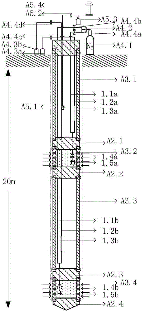
[0066] Example 1: U-shaped tube subsurface fluid layered sampling device suitable for shallow 20m level, including

[0067] Subsurface fluid intake subsystem, including:

[0068] 1.1a—the first drive tube 1.1b—the second drive tube; (catheter with an outer diameter of 8mm, PU-08);

[0069] 1.2a—the first sample tube; 1.2b—the second sample tube; (catheter with an outer diameter of 8mm, PU-08);

[0070] 1.3a—the first storage container; 1.3b—the second storage container; (depending on the single sampling capacity, such as volume 200ml);

[0071] 1.4a—the first liquid phase one-way valve; 1.4b—the second liquid phase one-way valve; (connected to the first shallow drive pipe, the circulation medium is underground fluid, only conduction from bottom to top, and always closed from top to bottom );

[0072] 1.5a—the first filter element; 1.5b—the second filter element; (the filtered particle size level is 35 microns, which is equivalent to a filter screen of 500 mesh, according ...

Embodiment 2

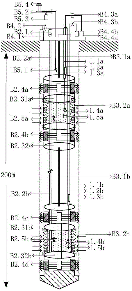
[0094] Example 2: U-shaped tube underground fluid stratified sampling device suitable for 200m level in middle strata,

[0095] Below in conjunction with accompanying drawing, the present invention is described in further detail:

[0096] Subsurface fluid intake subsystem, including:

[0097] 1.1a—the first drive tube; 1.1b—the second drive tube; (1 / 8 stainless steel tube, Swagelok);

[0098] 1.2a—the first sample tube; 1.2b—the second sample tube; (1 / 8 stainless steel tube, Swagelok);

[0099] 1.3a—the first storage container; 1.3b—the second storage container; (depending on the single sampling capacity, such as volume 500ml);

[0100] 1.4a—the first liquid phase one-way valve; 1.4b—the second liquid phase one-way valve; (connected to the first drive pipe, the circulation medium is underground fluid, only conduction from bottom to top, and always closed from top to bottom);

[0101] 1.5a—the first filter element; 1.5b—the second filter element; (the particle size level o...

Embodiment 3

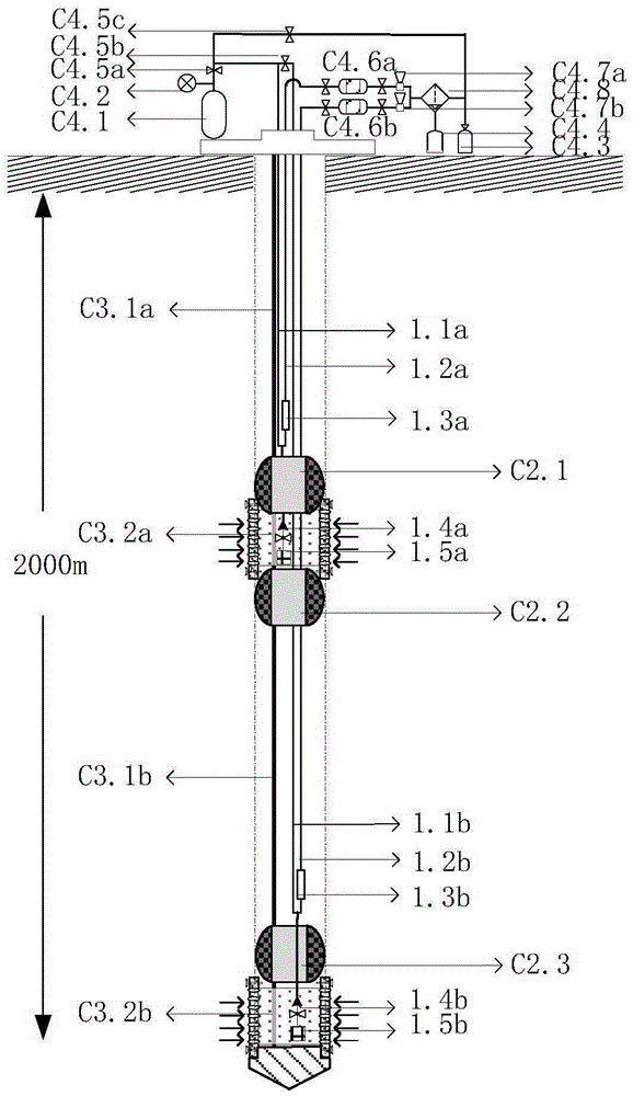
[0128] Example 3: U-shaped tube underground fluid layered sampling device suitable for 2000m deep strata, such as image 3 shown.

[0129] Subsurface fluid intake subsystem, including:

[0130] 1.1a—the first drive tube; 1.1b—the second drive tube; (1 / 8 stainless steel tube, Swagelok);

[0131] 1.2a—the first sample tube; 1.2b—the second sample tube; (1 / 8 stainless steel tube, Swagelok);

[0132] 1.3a—the first storage container; 1.3b—the second storage container; (depending on the single sampling capacity, such as volume 500ml);

[0133] 1.4a—the first liquid phase one-way valve; 1.4b—the second liquid phase one-way valve; (connected to the first drive pipe, the circulation medium is underground fluid, only conduction from bottom to top, and always closed from top to bottom);

[0134]1.5a—the first filter element; 1.5b—the second filter element; (the particle size level of the filter depends on the particle size distribution of the soil on site d 10 choose).

[0135] T...


PUM


Abstract

The invention discloses an underground fluid laminated sampling device based on a U-shaped pipe technology. The underground fluid laminated sampling device comprises an underground fluid sample injection subsystem, a packer subsystem, a chaining subsystem, a ground sampling subsystem and a soil gas sampling subsystem, wherein the underground fluid sample injection subsystem comprises a driving pipe, a sample discharging pipe, a fluid storage container, a liquid phase check valve and a filtering element; the soil gas sampling subsystem comprises a gas phase check valve arranged at a set position; the gas phase check valve is connected with a manual pump through a pneumatic ball valve and a gas sampling bag. The invention further discloses an underground fluid laminated sampling method based on the U-shaped pipe technology. The underground fluid laminated sampling device is novel in structural design; multiple technical difficulties are overcome; compared with a product of the original technology, the underground fluid laminated sampling device has the advantages that the working performance, the application range and the system stability are greatly improved, has higher competitiveness and industrial leading superiority, can be widely applied, is good in engineering demand, and has good application prospect and commercial value.

Description

technical field [0001] The present invention relates to the field of underground fluid sampling, in particular to an underground fluid layered sampling device based on U-shaped tube technology, and also specifically to a method for underground fluid layered sampling based on U-shaped tube technology, and a method for realizing layered sampling of underground fluids at different formation depths series of devices. Background technique [0002] Subsurface fluid is an important factor related to the evolution of the earth and the survival of surface organisms. Subsurface fluid sampling can continuously provide a large amount of physical, chemical and microbial information about the formation through isotope tracking, formation residual gas analysis, chemical composition testing, microbial community characteristics and other analysis methods, which is of great guiding significance for engineering development and environmental safety assessment One of the means of monitoring. ...

Claims


Application Information

Patent Timeline
Patent Type & Authority Applications(China)
IPC IPC(8): E21B49/08
Inventor 李小春刘学浩李琦方志明宋然然肖威魏宁
Owner INST OF ROCK & SOIL MECHANICS CHINESE ACAD OF SCI
Why Eureka
Try Eureka