Excavation deviation processing method of raise-boring machine for deep vertical shaft

A raise drilling rig and processing method technology, applied in vertical well equipment, well sinking, earthwork drilling and other directions, can solve the problems of reducing slagging capacity, delaying construction period, failing to produce slag, etc., and achieve shortening construction period, strengthening strength, Reduces the effect of repeated drilling of pilot holes

Inactive Publication Date: 2016-02-03
SINOHYDRO BUREAU 7 CO LTD
View PDF4 Cites 16 Cited by
  • Summary
  • Abstract
  • Description
  • Claims
  • Application Information

AI Technical Summary

Problems solved by technology

The disadvantage is that the pilot hole deviates more or less from the design centerline of the vertical shaft due to complex engineering geology, weak interlayer, mechanical precision, and operating proficiency in the pilot hole of the raise drilling rig, and the pilot hole at the bottom of the shaft deviates from the lower level. The slag guide shaft drilled according to the pilot hole cannot be constructed outside the hole, and the pilot hole needs to be re-drilled. Secondly, when the slag guide shaft is offset beyond the excavation ...

Method used


Image

  • Excavation deviation processing method of raise-boring machine for deep vertical shaft
  • Excavation deviation processing method of raise-boring machine for deep vertical shaft
  • Excavation deviation processing method of raise-boring machine for deep vertical shaft

Examples


Embodiment Construction

[0026] The present invention is specifically described below through the examples, the examples are only used to further illustrate the present invention, and cannot be interpreted as limiting the protection scope of the present invention, some non-essential improvements made by those skilled in the art according to the contents of the present invention And adjustments also belong to the protection scope of the present invention.

[0027] combine Figure 1 to Figure 16 .

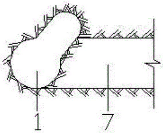
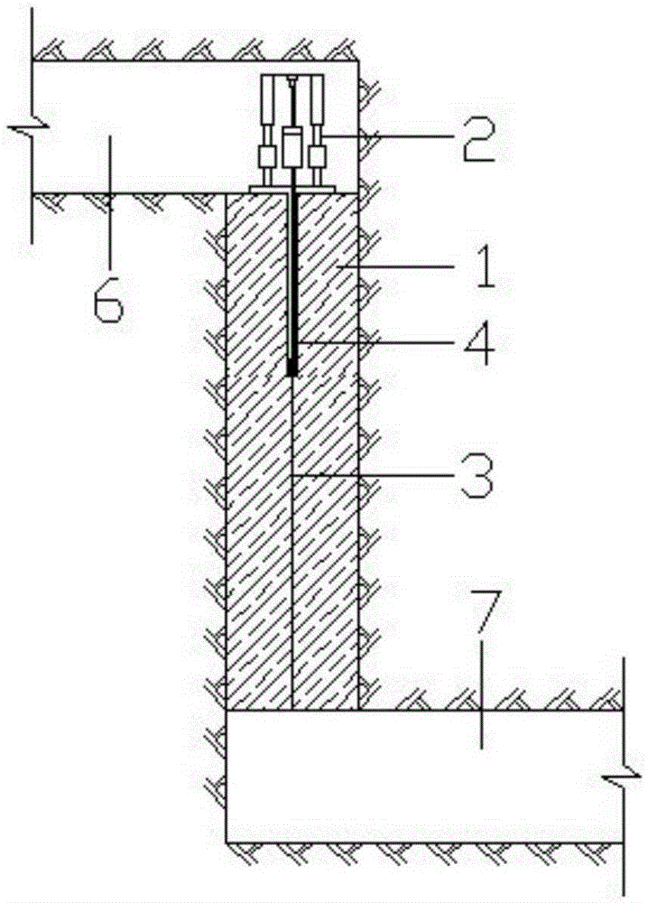
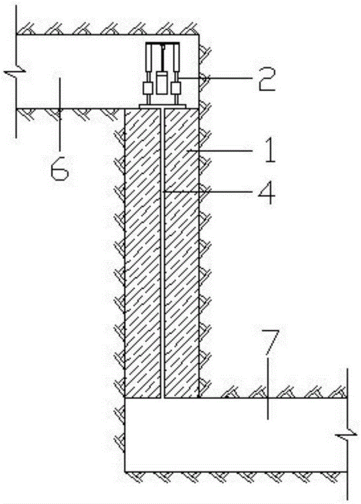
[0028] The process of excavating a vertical shaft using a raise drilling rig: when the upper level hole 6 and the lower level hole 7 are excavated during the excavation of the vertical shaft 1, use the raise drilling rig 2 to excavate from the top of the vertical shaft 1 in the upper level hole 6 The center line 3 drills the pilot hole 4 from top to bottom, and the position of the drill bit can be calculated according to the inclination angle of the drill pipe, the length of the drill pipe, and the depth of...


PUM


Abstract

The invention discloses an excavation deviation processing method of a raise-boring machine for a deep vertical shaft. The method includes the steps that the position of a pilot hole tail end drill is determined according to the drill stem deviation angle, the vertical shaft height and other parameters, and a mucking pilot shaft and a muck discharging channel are formed through expanding excavation; then, after the mucking pilot shaft is formed, the vertical shaft is excavated in a drilling and blasting mode, and when the mucking pilot shaft deviates and loses the mucking function or mucking is unsmooth, expanding excavation is performed on the part between the vertical shaft and the mucking pilot shaft so that the mucking pilot shaft can perform mucking effectively and smoothly; after exaction is completed, the deviation expanding excavation part is backfilled so that the verticality of the vertical shaft can be guaranteed and the requirement of pressure steel pipe installation for the verticality of the vertical shaft can be met. According to the method, under the condition that a pilot hole deviates, it is guaranteed that the mucking pilot shaft performs mucking effectively, and the verticality of the vertical shaft is also guaranteed; in pressure vertical shaft or surge shaft construction in water conservancy and hydropower engineering, the method has the advantages of reducing repeated drilling extraction of a pilot hole, shortening the construction period and improving the strength of a backfilled region behind a pressure steel pipe at the bottom of a pressure vertical shaft, and therefore the method can be widely applied to small-diameter deep vertical shaft or inclined shaft construction with a short construction period.

Description

technical field [0001] The invention belongs to the field of engineering construction, in particular to the field of deep shaft excavation, in particular to a method for processing the excavation offset of a deep shaft raise drilling rig. Background technique [0002] The traditional construction method for the excavation of water conservancy and hydropower pressure shafts, surge shafts and coal mine shafts is to measure and locate from top to bottom, and manually drill and blast excavation. Although this method has high precision, only one volley surface blasting effect is not good, and the slag is discharged when hoisting Inconvenience, the incidence of falling accidents, high risk, long construction period and high cost. At present, the common construction method in the excavation of deep shafts is: use a raise drilling rig to drill and excavate the slag guide shaft from the upper level hole along the center line of the shaft to connect the lower level hole, measure and l...

Claims


Application Information

Patent Timeline
IPC IPC(8): E21D1/00E21D3/00
Inventor 向建吴旭姚坤
Owner SINOHYDRO BUREAU 7 CO LTD
Why Eureka
Try Eureka