Electro-hydraulic valve control displacement module and using method thereof

An electro-hydraulic valve and displacement technology, applied in the hydraulic field, can solve problems such as low precision, complex structure, and difficult maintenance, and achieve the effect of meeting highly accurate work requirements, accurate flow adjustment, and low change accuracy

Active Publication Date: 2016-02-03
SHANDONG UNIV OF SCI & TECH
View PDF10 Cites 1 Cited by
  • Summary
  • Abstract
  • Description
  • Claims
  • Application Information

AI Technical Summary

Problems solved by technology

Utilizing this characteristic, the input current of the pump can be changed, and the output flow of the pump can be reduced, so that the commutation is softer and the system impact is smaller when commutating, but the structure of the invention is complicated, and two magnetostrictive sensors are installed on two The interior of the piston rod is relatively difficult, and the present invention cannot achieve the purpose of precisely controlling the displacement
[0004] In the hydraulic system applied to construction machinery, due to the large change in the flow required by each actuator within a working cycle and the high precision required, such as the variable plunger pump of the hydraulic system in the excavator, in different working conditions, the plunger pump Different flow changes are required, and the inclination angle of the swash plate needs to be changed accordingly. In the past, it was adjusted by purely mechanical structure feedback. Its structure is complicated, its precision is low, and its maintenance is difficult.

Method used


Image

  • Electro-hydraulic valve control displacement module and using method thereof
  • Electro-hydraulic valve control displacement module and using method thereof
  • Electro-hydraulic valve control displacement module and using method thereof

Examples


Embodiment 1

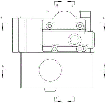
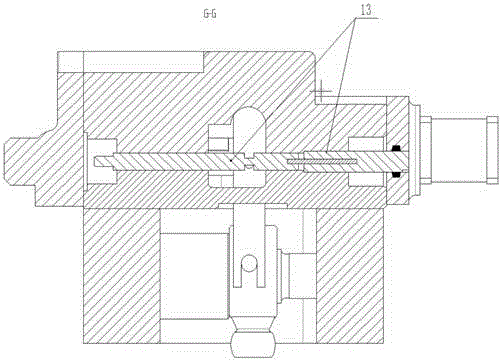
[0033] Such as Figure 2 to Figure 10b As shown, an electro-hydraulic valve-controlled displacement module includes a housing 4. End caps I5 and II6 are installed on both sides of the housing 4 respectively. The housing 4 is assembled into a sealed structure and installed on one side of the housing 4. A stepping motor 1, the stepping motor 1 is a Haydn 3500 series linear stepping motor, and a transmission rod 17, a feedback connecting rod 11, a three-position three-way valve, a linear variable differential transformer 13, a differential The dynamic cylinder 10 and the differential cylinder liner 9. In this embodiment, the linear variable differential transformer adopts the 0500MHR-018 sensor of Antai Electronics, and the bottom of the shell 4 is provided with a base 8 connected with the shell. The cylinder and the differential cylinder liner 9 are placed in the base 8; the output shaft of the stepping motor 1 penetrates into the housing 4 and is threadedly connected with one e...

Embodiment 2

[0041] An electro-hydraulic valve-controlled displacement module, the structure of which is as described in Embodiment 1, the difference is that the output shaft of the stepper motor 1 is connected to one end of the transmission rod 17 through a coupling.

Embodiment 3

[0043] A method for using an electro-hydraulic valve-controlled displacement module, comprising the following steps,

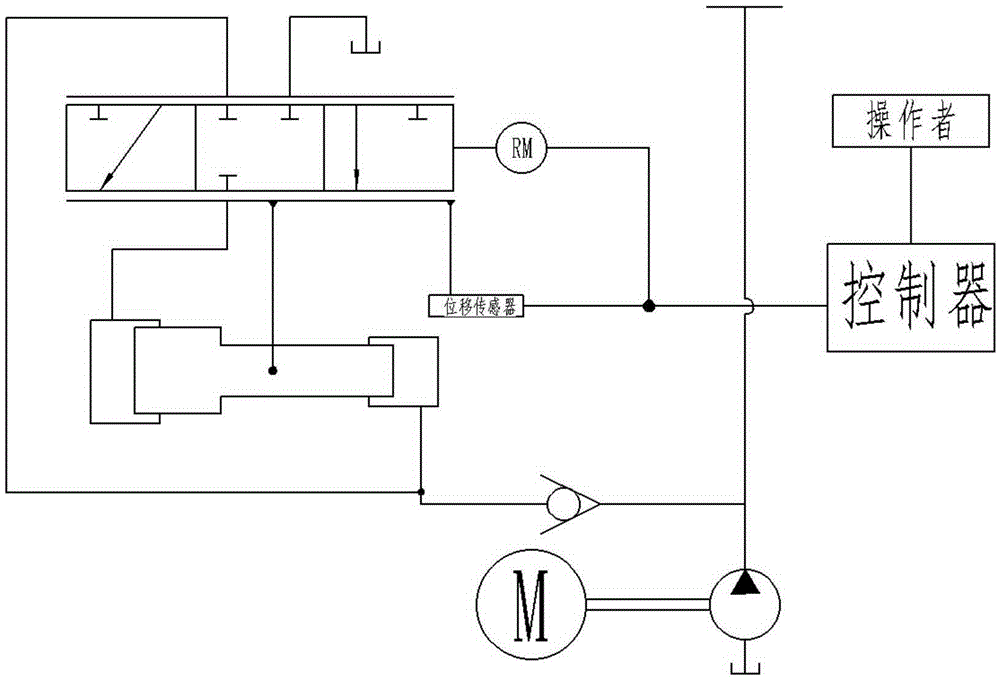
[0044] When the operator wants to change the working status, he starts the stepper motor 1, and the output shaft of the stepper motor 1 drives the transmission rod 17 to move. The rotation of the transmission rod 17 is limited, so that the transmission rod 17 can smoothly and accurately transmit the displacement of the stepper motor 1, and the movement of the stepper motor 1 leads to the movement of the feedback link 11 through the transmission rod 17. At this time, the feedback link 11 The lower fulcrum (the cylindrical pin 12 connected with the almost cylinder liner) does not move, and the feedback connecting rod 11 uses this as the fulcrum to form a lever, and then the spool 2 of the three-position three-way valve connected to the upper end of the feedback connecting rod 11 moves to control The operation of the three-position three-way valve makes the diffe...


PUM


Abstract

The invention relates to an electro-hydraulic valve control displacement module and a using method thereof. The electro-hydraulic valve control displacement module comprises a stepping motor, a transmission rod, a feedback connecting rod, a three-position three-way valve, a linear variable differential transformer, a differential cylinder and a differential cylinder sleeve. The stepping motor is in transmission connection with the transmission rod. The differential cylinder sleeve is fixedly connected with the differential cylinder. The top end of the feedback connecting rod is hinged to the three-position three-way valve, and the bottom end of the feedback connecting rod is hinged to the differential cylinder sleeve. The two sides of the feedback connecting rod are hinged to the transmission rod and the linear variable differential transformer respectively. By means of the linear variable differential transformer and the feedback connecting rod, motion information of the stepping motor and the differential cylinder is fed back to a single-chip microcomputer in real time, by means of accurate calculation of the single-chip microcomputer, the displacement relation between the stepping motor and the differential cylinder can be accurately controlled, an operator can control the displacement relation conveniently and accurately, and therefore accurate adjustment is achieved.

Description

technical field [0001] The invention relates to an electro-hydraulic valve-controlled displacement module and a using method thereof, belonging to the technical field of hydraulic pressure. Background technique [0002] As an important part of hydraulic components, control valves are widely used in real life and construction machinery, and displacement control valves are one of the most widely used ones. However, different valves have different functions in different occasions. With the development of science and technology, electronic control systems are gradually applied to traditional purely mechanical structural components, making certain tasks easier. [0003] Chinese patent document CN203009444U discloses a new type of electronically controlled pumping oil cylinder based on magnetostrictive sensors, including two magnetostrictive sensors and two oil cylinders, and the magnetic rulers of the two magnetostrictive sensors are installed on the pistons of the two oil cylind...

Claims


Application Information

Patent Timeline
Patent Type & Authority Applications(China)
IPC IPC(8): F15B13/02F16K31/04F16K31/12
CPCF15B13/02F16K31/04F16K31/12
Inventor 曾庆良李伟民王成龙逯振国王认辉王统诚杨扬王刚刘文超
Owner SHANDONG UNIV OF SCI & TECH
Why Eureka
Try Eureka