A heat pipe vapor chamber and manufacturing method thereof

A manufacturing method and vapor chamber technology, which are applied to indirect heat exchangers, lighting and heating equipment, electrical components, etc., can solve the problem of large contact thermal resistance between the capillary structure and the inner surface of the shell, poor heat dissipation capacity of the heat pipe vapor chamber, and the like. Problems such as steam flow obstruction in the support structure, to achieve the effect of easy promotion, easy operation, and simple operation

Inactive Publication Date: 2018-04-17
UNIV OF ELECTRONICS SCI & TECH OF CHINA
View PDF6 Cites 0 Cited by
  • Summary
  • Abstract
  • Description
  • Claims
  • Application Information

AI Technical Summary

Problems solved by technology

[0004] At present, various forms of heat pipe vapor chambers have been proposed. The existing heat pipe vapor chambers mainly have the following problems: the contact thermal resistance between the capillary structure and the inner surface of the shell is too large, the support structure hinders the flow of steam, and the capillary Poor permeability caused by insufficient force or excessive capillary force
These problems will eventually make the heat dissipation ability of the heat pipe vapor chamber worse

Method used


Image

  • A heat pipe vapor chamber and manufacturing method thereof
  • A heat pipe vapor chamber and manufacturing method thereof
  • A heat pipe vapor chamber and manufacturing method thereof

Examples


Embodiment Construction

[0034] The present invention will be further described below in conjunction with accompanying drawing and specific embodiment:

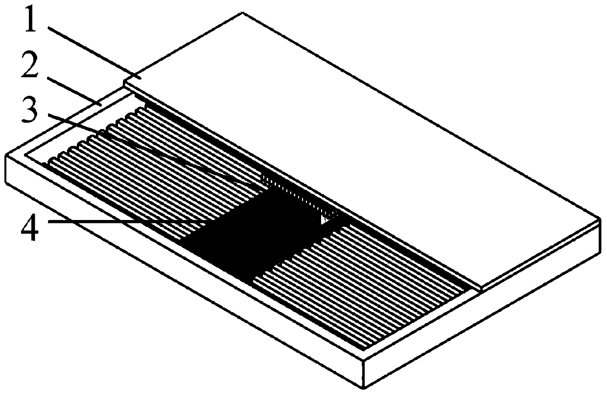
[0035] Such as figure 1 As shown, the structure diagram of the heat pipe vapor chamber of the present invention includes an upper cover 1 , a bottom box 2 and a porous capillary core assembly. The upper cover 1 and the bottom box 2 form a sealed packaging cavity, and the inside of the packaging cavity is evacuated and filled with working fluid. The porous capillary core assembly is located in the middle of the packaging cavity, and is connected to the lower surface of the upper cover 1 and the upper surface of the bottom box 2 respectively. The lower surface of the upper cover 1 is provided with first channels 5, and the first channels 5 are distributed on both sides of the porous capillary core assembly. The upper surface of the bottom box 2 is provided with second channels 6, and the second channels 6 are also distributed on both sides of the por...


PUM


Abstract

The invention discloses a heat pipe soaking plate and a manufacturing method thereof. The heat pipe soaking plate includes an upper cover and a bottom box forming a sealed packaging cavity, and a porous capillary core assembly, which is located in the middle of the packaging cavity and is respectively It is connected with the lower surface of the upper cover and the upper surface of the bottom box. The lower surface of the upper cover and the upper surface of the bottom box are respectively provided with a first channel and a second channel distributed on the left and right sides of the porous capillary core assembly. It is vacuumed and injected with working fluid; the manufacturing method of the heat pipe vapor chamber includes the steps of making an upper cover and a bottom box, making and fixing a porous capillary core component, cleaning and cavity sealing welding, liquid injection and sealing, and the like. The heat pipe vapor chamber provided by the present invention, through the special design of the liquid-absorbing core, accelerates the return flow of the working fluid, effectively improves the working efficiency, and has good heat transfer performance and heat dissipation capacity; the manufacturing method of the heat pipe vapor chamber provided by the present invention is simple Easy to operate.

Description

technical field [0001] The invention belongs to a heat dissipation device for microelectronic devices, and in particular relates to a thermal soaking plate for a heat pipe and a manufacturing method thereof. Background technique [0002] With the rapid development of microelectronics technology and the continuous improvement of chip integration and performance, more and more high-power chips have a continuous increase in heat dissipation. If the heat generated when the chip is running cannot be dissipated in time, it will affect its working stability, reduce the mean time between failures, and in severe cases, the chip will be burned. At the same time, the activities of transistors in different functional modules in the chip will cause highly uneven heat generation, which in turn will lead to hot spots in the chip that change with time and space, and hot spots will bring greater damage to the chip. However, the trend of chip miniaturization and integration will not change, ...

Claims


Application Information

Patent Timeline
Patent Type & Authority Patents(China)
IPC IPC(8): F28D15/04H01L23/427
Inventor 郝晓红黄洪钟彭倍管吉庆
Owner UNIV OF ELECTRONICS SCI & TECH OF CHINA
Why Eureka
Try Eureka