Method for synchronously triggering large-equivalent warhead static explosion experiment multi-parameter testing devices
A technology of static explosion test and test equipment, which is applied in the direction of offensive equipment, ammunition test, weapon accessories, etc. It can solve the problems of early trigger, heavy workload, and no trigger standard, etc., and achieve consistent synchronization of trigger zero point and easy implementation , the effect of improving reliability
- Summary
- Abstract
- Description
- Claims
- Application Information
AI Technical Summary
Problems solved by technology
Method used
Image
Examples
Embodiment 1
[0040] In the static explosion test of a large-equivalent warhead, various parameters of shock waves, seismic waves, and fragments were simultaneously deployed and tested in multiple directions within a 360° range centered on the blast center and within a distance of 1000m. . The shock wave overpressure test is basically triggered by an on-off target. Due to the long distance of the seismic wave, it is manually triggered. Wired layout is difficult to implement. At this time, the wireless synchronous triggering method of the present invention is used to trigger all test devices simultaneously. Since the detonation circuit time is closest to the warhead detonation time, the current generated by the detonation circuit is used as the trigger input signal source of the management center system, and the management center system (which can be one of the data acquisition devices) and a wireless transmitter connected to the management center system The antenna is arranged in a safety s...
Embodiment 2
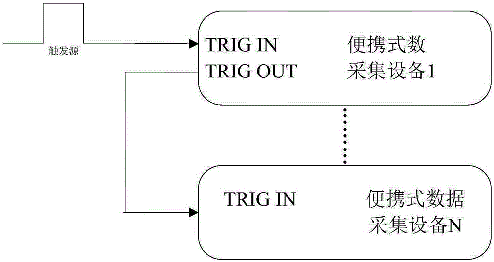
[0042] The static explosion test of a large-yield warhead needs to test various parameters such as shock waves and fragments. The number of sensors deployed is large and concentrated in one direction. In this case, multiple sets of data acquisition equipment can be put together. The trigger mode performs synchronous triggering. Only need to use short coaxial cables to connect multiple devices according to figure 2 Connect in order as shown, after connecting the wires, connect the trigger source signal to the TRIGIN interface of the first device, set the trigger mode to "external trigger", set the trigger edge, click "start acquisition", and the device enters the state of waiting for acquisition , when the set effective edge signal is generated on the TRIGIN interface, the trigger device will collect. This trigger mode is suitable for multi-channel and multiple sets of data acquisition equipment placed together for data acquisition, which saves equipment, is convenient to use...
Embodiment 3
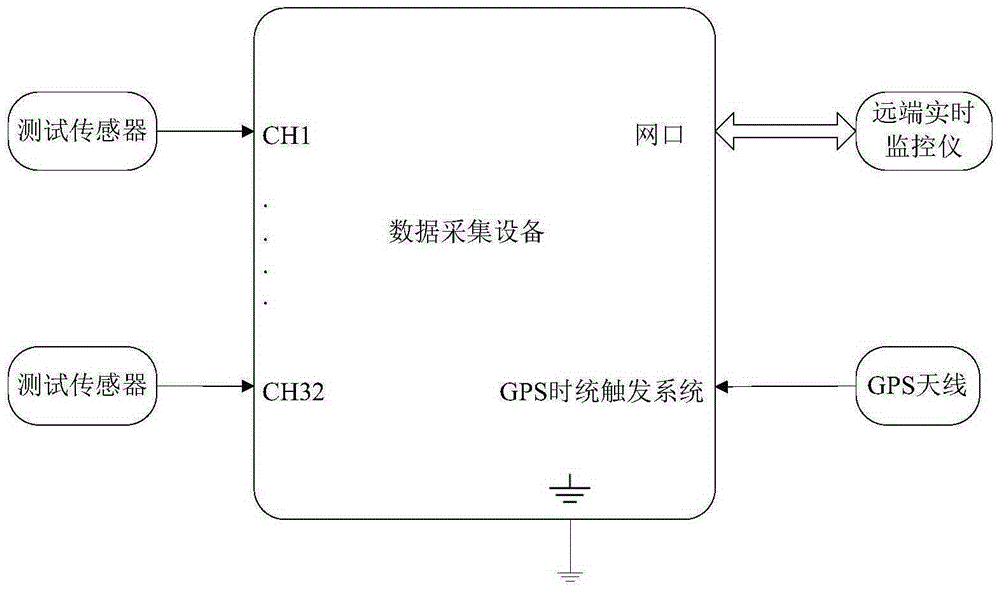
[0044] A static explosion test of a product requires that the product be detonated after being placed in the test site for 4 hours, and the detonation time has been determined. During the period from when the product is hoisted in place to detonation, according to safety requirements, personnel cannot approach the boundary of the test site. In this way, the data acquisition equipment can adopt the GPS timing trigger mode. The specific operation is: after connecting the data acquisition equipment, after the GPS synchronization light of the equipment is always on, set the trigger mode to "GPS timing trigger", after setting the GPS trigger time, click "Start acquisition", and the equipment enters the standby mode. State, when the device time is consistent with the set time, the trigger device will automatically trigger the collection. This triggering method is suitable for accurate timing detonation, which can reduce a lot of workload and ensure personnel safety.
PUM
 Abstract
Description
Claims
Application Information
 - R&D
- Intellectual Property
- Life Sciences
- Materials
- Tech Scout
- Unparalleled Data Quality
- Higher Quality Content
- 60% Fewer Hallucinations
Browse by: Latest US Patents, China's latest patents, Technical Efficacy Thesaurus, Application Domain, Technology Topic, Popular Technical Reports.
© 2025 PatSnap. All rights reserved.Legal|Privacy policy|Modern Slavery Act Transparency Statement|Sitemap|About US| Contact US: help@patsnap.com


