Hydraulic Control System of Pipe Feeder of Mixed Explosives Vehicle

A technology of a hydraulic control system and an explosive vehicle, applied in the field of hydraulic control systems, can solve the problems of destroying the fluid structure, increasing the deformation of the drug delivery tube 34, and failing to achieve pressure compensation, so as to ensure personal safety, high efficiency, and improve operating efficiency Effect

Active Publication Date: 2017-03-22
BEIJING BGRIMM YIBO TECH +1
View PDF4 Cites 0 Cited by
  • Summary
  • Abstract
  • Description
  • Claims
  • Application Information

AI Technical Summary

Problems solved by technology

Using the spring 32 for pressure compensation has a small compensation range and low control accuracy. When the compensation pressure of the spring 32 is too high, the deformation of the drug delivery tube 34 will be further increased, thereby destroying the fluid structure of the mixed explosive in the tube and affecting the charging effect. Even cause deformation and blockage; when the compensation pressure is too small, the purpose of pressure compensation cannot be achieved
[0007] With the development of underground mining technology and equipment, the requirements for the mechanization and automation of underground mixed explosives vehicles are constantly increasing, and the height of mining sections and the depth of upward blastholes are increasing. Operational efficiency and other aspects cannot meet the needs of production development. The hydraulic control system of the pipe feeder of the mixed explosive vehicle with the aforementioned functions plays an important role in realizing the mechanized automatic charging of underground mines.

Method used


Image

  • Hydraulic Control System of Pipe Feeder of Mixed Explosives Vehicle
  • Hydraulic Control System of Pipe Feeder of Mixed Explosives Vehicle
  • Hydraulic Control System of Pipe Feeder of Mixed Explosives Vehicle

Examples


Embodiment Construction

[0027] Reference will now be made in detail to embodiments of the invention, examples of which are illustrated in the accompanying drawings, wherein like reference numerals refer to like parts throughout.

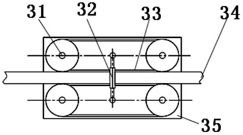
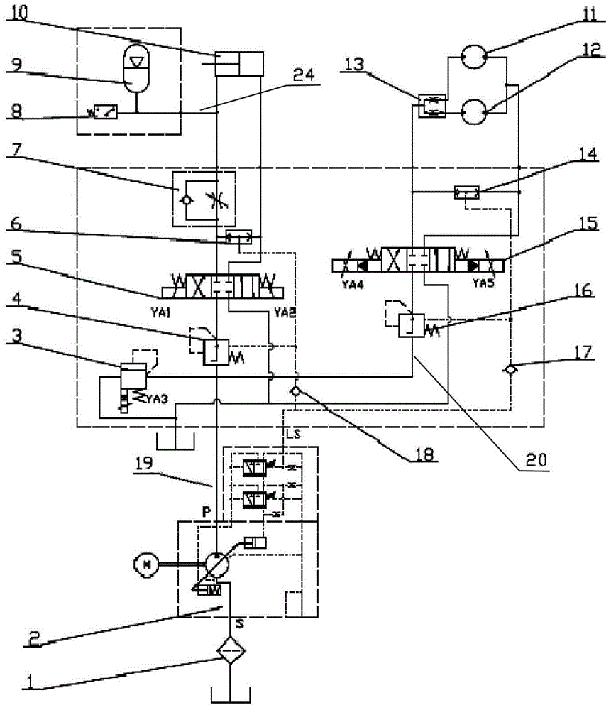
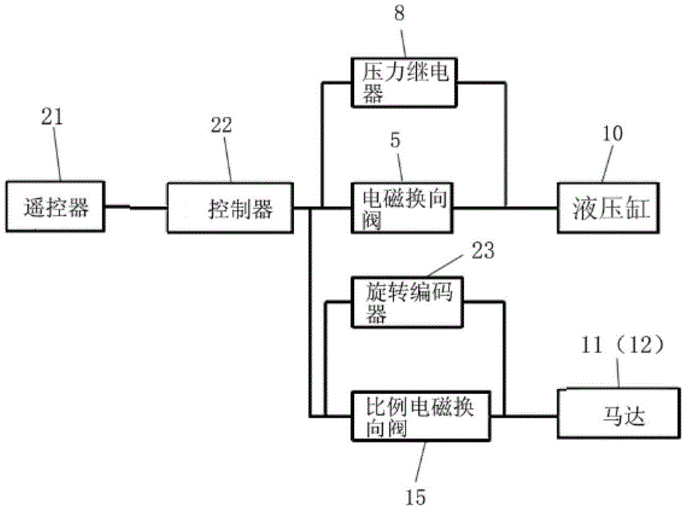
[0028] refer to Figure 2 to Figure 3 , according to an embodiment of the present invention, the provided hydraulic control system for the pipe feeder of the mixed explosive vehicle includes a hydraulic pump 2, a hydraulic cylinder 10, an electromagnetic reversing valve 5, two motors 11 and 12, a proportional electromagnetic reversing Directional valve 15, proportional electromagnetic overflow valve 3 and controller 22.

[0029] The hydraulic pump 2 is connected to the hydraulic cylinder 10 through the first oil passage 19, and a filter 1 can also be arranged between the hydraulic pump 2 and the oil tank. The hydraulic pump 2 may be a load sensitive variable hydraulic pump.

[0030] The electromagnetic reversing valve 5 is connected between the hydraulic pump 2 and the hy...


PUM


Abstract

The invention discloses a hydraulic control system for a pipe feeder of an explosive mixing and loading truck. The hydraulic control system comprises a hydraulic pump, a hydraulic cylinder, an electromagnetic reversing valve, two motors, a proportional electromagnetic reversing valve and a controller, wherein the hydraulic cylinder is connected with the hydraulic pump through a first oil channel; the electromagnetic reversing valve is connected between the hydraulic pump and the hydraulic cylinder and provided with two oil outlets connected to a rod cavity and a rodless cavity of the hydraulic cylinder respectively; the two motors are connected in parallel and connected with hydraulic pump through a second oil channel; the proportional electromagnetic reversing valve is connected between the hydraulic pump and the two motors and provided with two oil outlets connected to an oil inlet and an oil outlet of the two motors respectively; the controller controls actions of the electromagnetic reversing valve and the proportional electromagnetic reversing valve. The hydraulic control system provides enough clamping force within the allowable range of an explosive feeding pipe, conducts automatic pressure compensation according to changes of the clamping force to the explosive feeding pipe and improves the pipe feeding efficiency.

Description

technical field [0001] The invention relates to the technical equipment field of a mixed explosives vehicle, and more particularly relates to a hydraulic control system for a pipe feeder of a mixed explosives vehicle. Background technique [0002] The on-site mixed explosives vehicle is a special equipment for the production and charging of industrial explosives. Its function is to transport the semi-finished explosives produced by the ground station to the blasting site. After completing the subsequent production process on the vehicle, it is directly injected into the blast hole. After a certain reaction process, it becomes a finished explosive. For coal mines, black and non-ferrous underground mines that adopt the blasting mining method, on-site mixed explosives vehicles play an important role in realizing mechanized mining operations. [0003] Since underground mining blasting usually adopts the arrangement of upward fan-shaped blastholes, in order to prevent the blasth...

Claims


Application Information

Patent Timeline
Patent Type & Authority Patents(China)
IPC IPC(8): F42D1/10
Inventor 查正清田丰龚兵李鑫
Owner BEIJING BGRIMM YIBO TECH
Why Eureka
Try Eureka