Laser reception debugging method and apparatus

A debugging method and laser receiving technology, applied in the direction of radio wave measurement system, instrument, etc., can solve the problems that the installation and adjustment accuracy is difficult to meet the technical requirements, it is inconvenient for fault repair and field maintenance, and the adjustment direction cannot be determined, so as to shorten the installation and adjustment The effect of low time, worker skill level and experience requirements, precise and efficient assembly and adjustment

Active Publication Date: 2016-02-03
LUOYANG INST OF ELECTRO OPTICAL EQUIP OF AVIC
View PDF4 Cites 5 Cited by
  • Summary
  • Abstract
  • Description
  • Claims
  • Application Information

AI Technical Summary

Problems solved by technology

Since the photosensitive surface of the detector is too small, and the adjustment direction cannot be determined during the debugging process, very skilled workers are required to adjust the product, and it takes two

Method used


Image

  • Laser reception debugging method and apparatus
  • Laser reception debugging method and apparatus

Examples


Embodiment Construction

[0019] Embodiments of the present invention will be further described below in conjunction with the accompanying drawings.

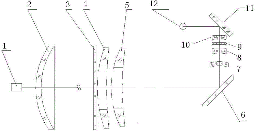
[0020] A specific embodiment of the laser receiving and debugging device of the present invention, such as Figure 1 to Figure 2 As shown, the debugging device includes an analog light source 1, a receiving optical path convergence and deflection system, and a detector bracket for installing a detector 12. The receiving optical path convergence and deflection system includes a fairing 2 arranged in sequence along the optical path from front to back, a protection Optical window 3, first receiving mirror 4, second receiving mirror 5, first reflecting mirror 6, third receiving mirror 7, fourth receiving mirror 8, optical filter 9, converging mirror group 10, second reflecting mirror 11, An endoscope capable of converting invisible light into visible light is installed on the detector bracket. The first receiving mirror 4 and the second receiving mirror 5 a...


PUM


Abstract

The invention relates to the optical adjusting field of a laser range finding machine, and specifically relates to a laser reception debugging method and apparatus. The laser reception debugging method comprises adjusting a reception light path; performing convergence and at least two-level replication for a laser echo signal generated after reflection of the signal emitted from the laser range finding machine through a detection object, and converging the laser echo signal at the photosensitive surface position of the detector eventually; setting an endoscope which can convert the invisible light into visible light, at the position of the photosensitive surface of the detector; and then adjusting the detector. The laser reception debugging method and apparatus can utilize the endoscope to display the invisible light as the visible light so that visual adjusting of a laser optical axis can be realized and accurate adjusting of the light path can be realized. The laser reception debugging method and apparatus can solve the problem about offset of the optical axis because of blind adjusting of laser optical axis, optical component machining error and adjusting error of an assembling staff, and has the advantages of being simple in operation, having no requirement for the skill level and the experience of workers, reducing the adjusting time, effectively improving the adjusting accuracy, and being able to realize accurate and effective adjusting of the laser optical axis.

Description

technical field [0001] The invention relates to the field of optical adjustment of laser distance measuring machines, in particular to a laser receiving and debugging method and a debugging device. Background technique [0002] At present, the laser receiving sensitivity adjustment mostly adopts the method of passing through the axis of visible light, but after the mechanical optical axis is passed through, when installing the optical parts, it is necessary to use a light source with a wavelength of 1064nm to adjust the product, and the light with a wavelength of 1064nm is invisible Yes, and the adjustment and processing errors of the optical lens will also cause a certain amount of offset of the optical axis, resulting in a large change in the optical axis of the machine that uses visible light in the early stage. The photosensitive surface of the detector is generally only 0.5-0.8mm in size. To make the system light spot converge on the center of the detector surface, it c...

Claims


Application Information

Patent Timeline
IPC IPC(8): G01S7/497
CPCG01S7/497
Inventor 李金全吴正华樊宪唐
Owner LUOYANG INST OF ELECTRO OPTICAL EQUIP OF AVIC
Why Eureka
Try Eureka