FPGA-based power electronic simulation system and method

A technology of power electronics and simulation methods, applied in the field of simulation, can solve problems such as slowing down simulation speed, high time cost, and inability to meet power electronic devices, so as to achieve the effect of improving simulation efficiency and saving simulation time

Active Publication Date: 2016-02-03
SHANGHAI KELIANG INFORMATION ENG
View PDF6 Cites 18 Cited by
  • Summary
  • Abstract
  • Description
  • Claims
  • Application Information

AI Technical Summary

Problems solved by technology

The admittance matrix of the power electronic system can be established by using the node analysis method. However, once the state of the circuit changes, for example, the state of the switch changes, the admittance matrix of the system must be recalculated. The time cost is high and the simulation is reduced. speed
[0006] Moreover, with the expansion of the scale of the power electronic system, there will be situations where the corresponding number of power electronic devices cannot be satisfied by relying on simulation resources.

Method used


Image

  • FPGA-based power electronic simulation system and method
  • FPGA-based power electronic simulation system and method
  • FPGA-based power electronic simulation system and method

Examples


Embodiment Construction

[0031] In order to make the object, technical solution and advantages of the present invention clearer, various embodiments of the present invention will be described in detail below in conjunction with the accompanying drawings. However, those of ordinary skill in the art can understand that, in each implementation manner of the present invention, many technical details are provided for readers to better understand the present application. However, even without these technical details and various changes and modifications based on the following implementation modes, the technical solution claimed in each claim of the present application can be realized.

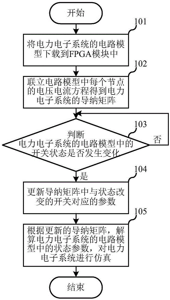
[0032] The first embodiment of the present invention relates to an FPGA-based power electronics simulation method, which is applied to power electronics system simulation, and the specific process is as follows figure 1 shown, including the following steps:

[0033] Step 101, download the circuit model of the power electron...


PUM


Abstract

The invention relates to the simulation technology field, and discloses an FPGA-based power electronic simulation system and method. The FPGA-based power electronic simulation method is applied to a power electronic system. The FPGA-based power electronic simulation method comprises the following steps: downloading a circuit model of a power electronic system in an FPGA module; connecting voltage and current equations of modes in the circuit model and obtaining an admittance matrix of the power electronic system, wherein the dimensions of the admittance matrix will not change along with changes of the switch state of a circuit in the power electronic system; updating corresponding parameters of switches that change in state in the admittance matrix if the switch state of the circuit in the power electronic system changes; and resolving state parameters of the circuit model of the power electronic system according to the updated admittance matrix, and simulating the power electronic system. In this way, an admittance matrix of a system is prevented from being re-calculated every time when the state of a switch changes. The simulation time is saved, and the simulation efficiency is improved.

Description

technical field [0001] The invention relates to the field of simulation technology, in particular to a power electronics simulation system and method based on FPGA (Field Programmable Gate Array). Background technique [0002] At present, in the field of real-time simulation of power systems, the low-frequency power electronics simulation technology for traditional power transmission and distribution systems has tended to be perfected, and the simulation system based on CPU (central processing unit, central processing unit) is mainly used. The simulation system based on this software environment of CPU has the advantages of simple operation, high maturity and low complexity. Today, CPU-based simulation systems have been widely used in real-time simulations for large-scale power grids and traditional power transmission and distribution systems. [0003] With the rise of smart grids, large-scale power electronics have been applied in new energy grid-connected, distributed pow...

Claims


Application Information

Patent Timeline
Patent Type & Authority Applications(China)
IPC IPC(8): G05B17/02
Inventor 陆臻业邹毅军王天民王佳王志鹏谭伟
Owner SHANGHAI KELIANG INFORMATION ENG
Why Eureka
Try Eureka