Solid laser with adjustable pulse width from hundred picoseconds to nanosecond

A solid-state laser, nanosecond pulse technology, applied in lasers, laser parts, phonon exciters, etc., can solve the problems of complex laser structure and high cost, and achieve the effect of good beam quality, simple structure and low technology

Inactive Publication Date: 2016-02-03
吕志伟
View PDF5 Cites 12 Cited by
  • Summary
  • Abstract
  • Description
  • Claims
  • Application Information

AI Technical Summary

Problems solved by technology

[0003] The purpose of the present invention is to solve the existing problems of using mode-locking technology combined with amplification technology to obtain narrow p

Method used


Image

  • Solid laser with adjustable pulse width from hundred picoseconds to nanosecond
  • Solid laser with adjustable pulse width from hundred picoseconds to nanosecond
  • Solid laser with adjustable pulse width from hundred picoseconds to nanosecond

Examples


specific Embodiment approach 1

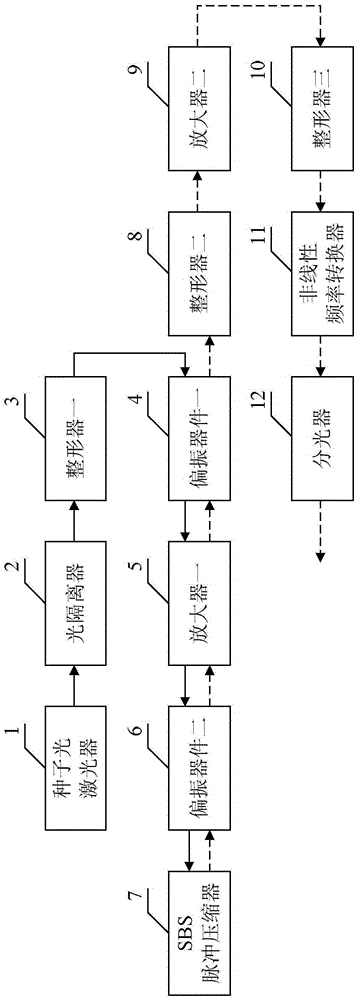
[0016] Specific implementation mode one: combine Figure 1 to Figure 9 , Figure 14 to Figure 17 Describe this embodiment mode, a solid-state laser with adjustable pulse width from picoseconds to nanoseconds described in this embodiment mode includes a seed optical laser 1, an optical isolator 2, a shaper 3, a polarization device 4, and an amplifier 1 5. Polarization device two 6, SBS pulse compressor 7, shaper two 8 and amplifier two 9;

[0017] The linearly polarized light generated by the seed light laser 1 passes through the optical isolator 2, the shaper one 3, the polarizer one 4, the amplifier one 5 and the polarizer two 6 in turn, enters the SBS pulse compressor 7, and returns from the SBS pulse compressor 7 After passing through the polarization device 2 6, the amplifier 1 5, the polarization device 1 4, the shaper 2 8 and the amplifier 2 9 in turn, the light exits from the amplifier 2 9;

[0018] Polarizing device one 4 is used to transmit the laser light polarized...

specific Embodiment approach 2

[0021] Specific implementation mode two: combination figure 1 Describe this embodiment. This embodiment is a further limitation of the solid-state laser with adjustable pulse width from 100 picoseconds to nanoseconds described in Embodiment 1. In this embodiment, the solid-state laser also includes a shaper 3 10 , nonlinear frequency converter 11 and beam splitter 12, the laser light emitted from amplifier two 9 passes through shaper three 10, nonlinear frequency converter 11 and beam splitter 12 in sequence, and then emerges from beam splitter 12.

[0022] After the laser light emitted from the amplifier two 9 passes through the shaper three 10, the nonlinear frequency converter 11 and the beam splitter 12 in sequence, the combined output of different laser wavelengths can be obtained.

specific Embodiment approach 3

[0023] Specific Embodiment 3: This embodiment is a further limitation of the solid-state laser with adjustable pulse width from one hundred picoseconds to nanoseconds described in Embodiments 1 and 2. In this embodiment, the working substance of the SBS pulse compressor 7 gas, liquid or solid.


PUM


Abstract

The invention relates to a solid laser with adjustable pulse width from a hundred picoseconds to a nanosecond and solves problems of complicated structure and high cost of a narrow-pulse-width large-energy laser structure obtained by means of a mode-locking technique in combination with amplification technology. Linear polarized light generated by a seed light laser successively passes an isolator, a shaper 1, a polarization device 1, an amplifier 1, and a polarization device 2 and then enters a SBS pulse compressor. Light returned from the SBS pulse compressor successively passes the polarization device 2, the amplifier 1, the polarization device 1, the shaper 2 and the amplifier 2 and then exits from amplifier 2. The solid laser is simple in structure, lower in cost compared with a product in the prior art, large in output energy, good in the quality of output light beams, and suitable for the fields of laser medicine, nonlinear optics, precision machining and laser communication.

Description

technical field [0001] The invention relates to a solid-state laser, in particular to a solid-state laser with adjustable pulse width from picoseconds to nanoseconds, and belongs to the field of lasers. Background technique [0002] Solid-state lasers with narrow pulse width and high energy have broad application prospects in the fields of laser medicine, nonlinear optics, precision processing and laser communication. At present, in order to obtain the output of sub-nanosecond or picosecond pulses with greater energy, it is often necessary to use semiconductor saturable absorbing mirror (SESAM) mode-locking technology to obtain nano-joule-level mode-locked sequences, and then combine regenerative amplifiers to obtain millijoule output. , and finally the pulse is further amplified by a traveling wave amplifier. The structure of this method is relatively complicated, and the regenerative amplifier has higher requirements for signal control, and the price is relatively expensi...

Claims


Application Information

Patent Timeline
IPC IPC(8): H01S3/223H01S3/083H01S3/034
Inventor 吕志伟王雨雷
Owner 吕志伟
Why Eureka
Try Eureka