High-voltage line inspection robot

A technology for inspection robots and high-voltage lines, applied in manipulators, overhead line/cable equipment, manufacturing tools, etc., can solve the problems of high line inspection costs, heavy workload, difficulties, etc. Service life, the effect of reducing energy loss

Active Publication Date: 2016-02-03
SHENZHEN JINGZHI MACHINE
4 Cites 28 Cited by

AI-Extracted Technical Summary

Problems solved by technology

[0003] At present, the commonly used inspection method is the manual inspection method. This method has a large workload, difficult conditions, and low inspection accuracy. Inspection items are difficult to complete by conventional methods
In order to achieve the purpose of comprehensive inspection, the inspection method of helicopter aerial survey has appeared, which has high accur...

Abstract

The invention discloses a high-voltage line inspection robot which comprises an integral supporting frame. The integral supporting frame is provided with a main controller and a power supply. The upper end surface of the integral supporting frame is provided with an image acquiring mechanism and two sliding mechanisms. The upper end of each sliding mechanism is provided with a driving mechanism, and the lower end is provided with a clamping mechanism. A high-voltage line channel is formed between the clamping mechanism and the driving mechanism. When bestriding of an obstacle is required, the driving mechanism and the clamping mechanism can be driven to rotate through the sliding mechanism, thereby reducing control difficulty in bestriding the obstacle. Through the clamping mechanism and the driving mechanism, a clamping force of the high-voltage line inspection robot to a high-voltage power transmission line can be effectively controlled, and furthermore the high-voltage line inspection robot can climb on a certain slope. Furthermore when obstacle bestriding is required, one end, which is separated from the high-voltage power transmission line, of the driving wheel of the device may reduce by a certain height, and the driving wheel can be re-attached with the high-voltage power transmission line through an elevating mechanism.

Application Domain

Technology Topic

Image

  • High-voltage line inspection robot
  • High-voltage line inspection robot
  • High-voltage line inspection robot

Examples

  • Experimental program(1)

Example Embodiment

[0055] The concept, specific structure and technical effects of the present invention will be clearly and completely described below with reference to the embodiments and accompanying drawings, so as to fully understand the purpose, characteristics and effects of the present invention. Obviously, the described embodiments are only a part of the embodiments of the present invention, rather than all the embodiments. Based on the embodiments of the present invention, other embodiments obtained by those skilled in the art without creative efforts are all within the scope of The scope of protection of the present invention. In addition, all the coupling/connection relationships mentioned in the text do not mean that the components are directly connected, but refer to a better coupling structure by adding or reducing coupling accessories according to specific implementation conditions.
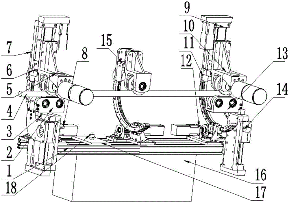
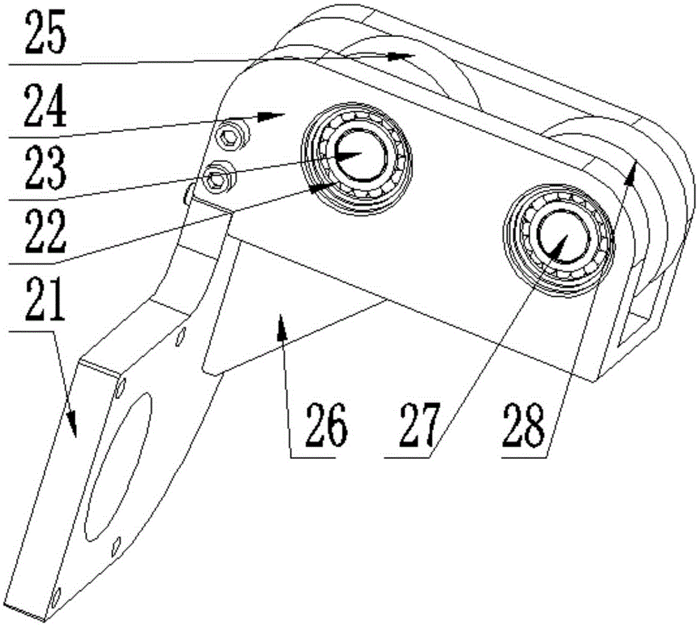
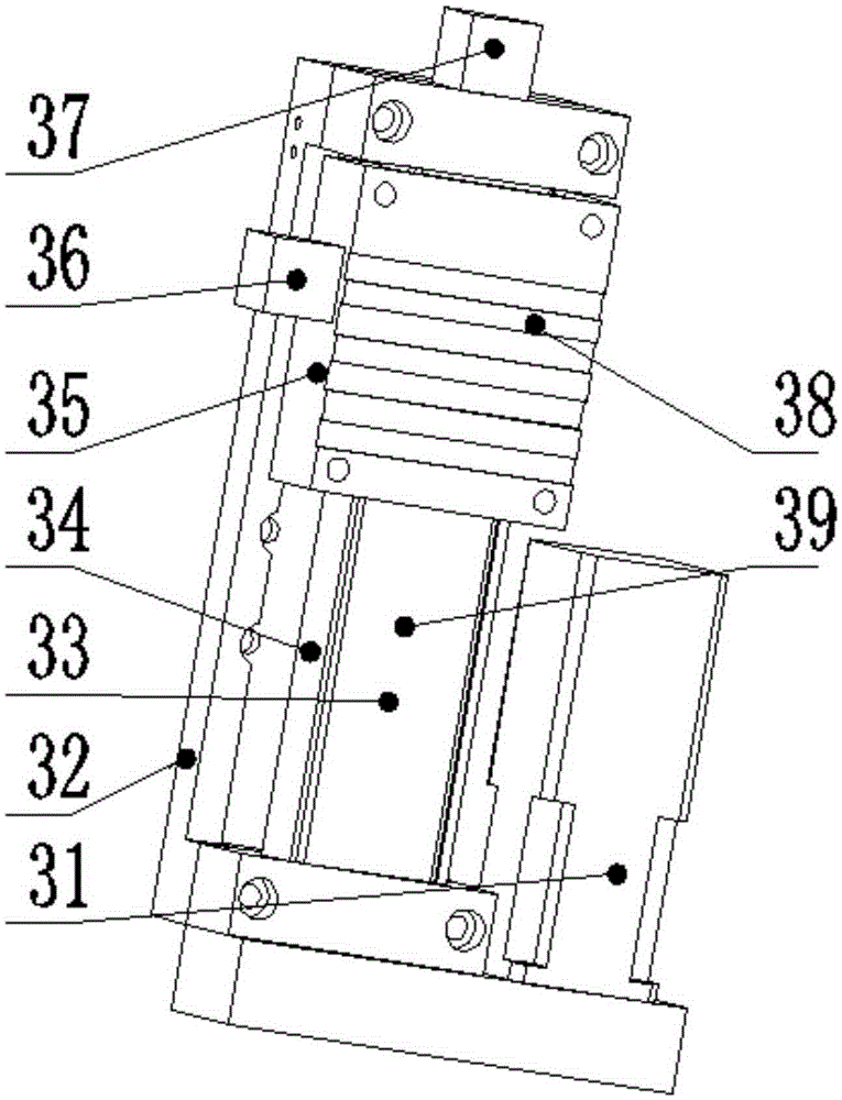
[0056] refer to Figure 1 to Figure 10 , a high-voltage line inspection robot, which includes an integral support frame 1 made of aluminum profiles, the lower end surface of the integral support frame 1 is provided with a main controller and a power supply, and the upper end surface of the integral support frame 1 is provided with a An image acquisition mechanism 18 and two sliding mechanisms 8, the two sliding mechanisms 8 are respectively located at both ends of the overall support frame 1, the image acquisition mechanism 18 is located between the two sliding mechanisms 8, and the upper end of the sliding mechanism 8 is provided with a driving mechanism 5. The lower end of the sliding mechanism 8 is provided with a clamping mechanism 2, and a high-voltage wire channel is formed between the clamping mechanism 2 and the driving mechanism 5. The sliding mechanism 8, the first lifting mechanism 3, the second lifting mechanism 6, The actions of the clamping mechanism 2 and the driving mechanism 5 are controlled by the main controller.
[0057] Further as a preferred embodiment, the upper end of the sliding mechanism 8 is connected to the driving mechanism 5 through the second lifting mechanism 6, and the lower end of the sliding mechanism 8 is connected to the clamping mechanism 2 through the first lifting mechanism 3. The sliding mechanism 8 can be The first lifting mechanism 3 and the second lifting mechanism 6 are driven to reciprocate, the first lifting mechanism 3 can drive the clamping mechanism to move in a straight line, the second lifting mechanism 6 can drive the driving mechanism to move in a straight line, and the sliding mechanism 8. The support frame 85, the slide rail support 86, the encoder support 88 and the motor support 91 fixed on the integral support frame 1, the slide rail support 86 is fixedly connected to the support frame 85, and the slide rail support 86 is slidably connected There is an arc-shaped slide rail 84, one side of the slide rail 84 is fixedly connected to the arc-shaped large gear 87, the large gear 87 is meshed with a pinion gear 90, and both ends of the pinion gear 90 pass through the first gear respectively. The bearing 82 is rollingly connected to the encoder bracket 88 and the motor bracket 91, one end of the pinion 90 is connected to the stepper motor 83 of the sliding mechanism on the motor bracket through the coupling 81, and the other end of the pinion 90 is connected through the coupling. The encoder 81 is connected to the encoder 89 of the encoder bracket 88 , and the first lifting mechanism 3 and the second lifting mechanism 6 are respectively fixed on both ends of the slide rail 84 .
[0058] Further as a preferred embodiment, the clamping mechanism 2 includes a clamping vertical plate 21 fixed on the moving platform of the first lifting mechanism 3, and the clamping vertical plate 21 connects the two clamping plates through the clamping connecting plate 26. The horizontal plate 24, the first clamping shaft 23 and the second clamping shaft 27 are installed between the two clamping transverse plates 24 through the rolling bearing 22, and the first clamping shaft 23 and the second clamping shaft 27 are mounted on the first clamping shaft 23 and the second clamping shaft 27 The first clamping wheel 25 and the second clamping wheel 28 are respectively fixed.
[0059] Further as a preferred embodiment, the driving mechanism 5 is fixed to the moving platform of the second lifting mechanism 6 through a driving connecting frame 55, and the driving connecting frame 55 is also fixed to the driving horizontal plate 54, and the driving horizontal plate 54 Both ends of the drive connecting plate 52 are provided with a drive connecting plate 52, the lower end of the drive connecting plate 52 is provided with a bearing support plate 51, a drive mechanism bearing 61 is installed on the bearing support plate 51, and a drive mechanism bearing 61 is provided inside the drive mechanism bearing 61. Mechanism shaft 60, the drive mechanism shaft 60 is provided with a driving wheel 53, the driving wheel 53 is located between the first clamping wheel 25 and the second clamping wheel 28, the driving wheel 53, the first clamping wheel 25 and the second clamping wheel 28. A high-voltage wire channel is formed between the clamping wheels 28, one end of the drive mechanism shaft 60 is connected to the drive motor shaft of the drive motor 56 through the drive mechanism coupling 59, and the drive motor 56 passes through the drive motor bracket 57 and the motor bracket fixing plate 58 Set on the drive connection board 52 .
[0060] Further as a preferred embodiment, the first lifting mechanism 3 includes a first lifting mechanism bracket 32 ​​fixed on the sliding mechanism 8, and one end of the first lifting mechanism bracket 32 ​​is provided with a first lifting mechanism motor 31, the The other end of the first lifting mechanism bracket 32 ​​is provided with a first infrared ranging sensor 37 , a first supporting frame 33 is provided inside the first lifting mechanism bracket 32 ​​, and second supporting frames 33 are provided on both sides of the first supporting frame 33 . A sliding arc 34, the first support frame 33 is provided with a first lead screw 39 and a first motion platform 35 sleeved on the first lead screw 39, and the first lifting mechanism bracket 32 ​​is also provided with a A first grating scale displacement sensor 36 for detecting the moving distance of the first motion platform 35, the first motion platform 35 is provided with a first pressure strain gauge 38 for sensing the pressing force on the first motion platform 35; The second lifting mechanism 6 includes a second lifting mechanism 6 bracket fixed on the sliding mechanism 8 , one end of the second lifting mechanism 6 bracket is provided with a second lifting mechanism 6 motor, and the inside of the second lifting mechanism 6 bracket is provided with a The second support frame, the two sides of the second support frame are provided with second sliding arcs, the inside of the second support frame is provided with a second lead screw and a second motion platform sleeved on the second lead screw, so The support of the second lifting mechanism 6 is also provided with a second grating ruler displacement sensor for detecting the moving distance of the second motion platform, and a second motion platform for sensing the pressing force on the second motion platform is provided on the second motion platform. Pressure strain gauges. The second lifting mechanism bracket is also provided with a second grating scale displacement sensor for detecting the moving distance of the second moving platform.
[0061] Further as a preferred embodiment, it also includes a first connecting frame 7 fixed on the second lifting mechanism 6, the first connecting frame 7 includes a connecting frame plate 71, and the upper end of the connecting frame plate 71 is fixed on the second lifting mechanism. The second lifting mechanism bracket of the mechanism 6, the lower end of the connecting frame plate 71 is provided with a connecting frame vertical plate 72, the connecting frame vertical plate 72 is provided with a connecting frame through hole 73, and is fixed to the large gear through the connecting frame through hole 73 87 or rail 84.
[0062] Further as a preferred embodiment, the integral support frame 1 is further provided with an intermediate support mechanism 15, the intermediate support mechanism 15 is arranged between the two sliding mechanisms 8, and the intermediate support mechanism 15 includes an auxiliary sliding mechanism 156, The upper end of the auxiliary sliding mechanism 156 is provided with a wheel bracket 154. The wheel bracket 154 is fixedly connected to the auxiliary sliding mechanism 156 through the auxiliary connecting frame 155. A support shaft 152 is installed in the wheel bracket 154. Both ends are rollingly connected to the wheel bracket 154 through the second bearing 153, the support wheel 151 is provided on the support shaft 152, and the structure of the auxiliary sliding mechanism 156 is the same as that of the sliding mechanism 8. The sliding mechanism 8 and the auxiliary sliding mechanism The mechanism 156 can move in the direction of the integral support frame 1 .
[0063] As a further preferred embodiment, the image capture mechanism 18 includes a camera 182 and a camera pan 181 that can rotate the camera 182 360°. The camera pan 181 is fixed to the overall support frame 1 through the support plate 16 .
[0064] Further as a preferred embodiment, the power supply and the main controller are installed in the control box 17, the power supply is installed in the form of block division, and the control box 17 is also provided with an accelerometer and an accelerometer for detecting the position state of the robot. Gyro sensor, the main controller adopts PC104 control board.
[0065] When the robot moves on the high-voltage transmission line, the image acquisition mechanism 18 can be used to determine the obstacles on the high-voltage transmission line, and then different obstacle-surmounting schemes can be formulated according to different obstacles, so that the robot can autonomously cross the high-voltage transmission line. different obstacles.
[0066] Taking spanning the spacer bar as an example, the use method of the present invention is specifically described,
[0067] 1. Place the robot on the high-voltage transmission line, and determine the distance between the two sliding mechanisms 8 and the auxiliary sliding mechanism 156 in the direction of the overall support frame 1 according to the size of the fixing hardware on the high-voltage transmission line, such as spacers and anti-vibration hammers.
[0068] 2. Control the movement of the drive motor in the drive mechanism 5 through the main controller, thereby driving the robot to move forward.
[0069] 3. The distance between the robot and the spacer bar is determined according to the infrared ranging sensor of the first lifting mechanism 3 or the camera 182 of the image acquisition mechanism 18. When the appropriate distance is reached, the robot stops moving and approaches the sliding mechanism 8 of the spacer bar. The first lifting mechanism 3 and the second lifting mechanism 6 drive the clamping mechanism 2 and the driving mechanism 5 to move away from the wire body.
[0070] 4. When the clamping mechanism 2 and the driving mechanism 5 reach the proper position driven by the first lifting mechanism 3 and the second lifting mechanism 6, the large gear 87 of the sliding mechanism 8 is rotated by a certain angle under the driving of the pinion 90, so that the driving Mechanism 5 and clamping mechanism 2 can avoid spacer bars.
[0071] 5. Control the motion of the drive motor in the drive mechanism 5 away from the spacer bar, so that the robot continues to move forward, so that the sliding mechanism 8 close to the spacer bar passes the spacer bar.
[0072] 6. The large gear 87 returns to the initial position driven by the pinion 90 .
[0073]7. The clamping mechanism 2 and the driving mechanism 5 return to the initial positions under the driving of the first lifting mechanism 3 and the second lifting mechanism 6 .
[0074] 8. Then the first lifting mechanism 3 and the second lifting mechanism 6 of the two sliding mechanisms 8 move at the same time, driving the control box 17 of the robot to move upward as a whole, so that the support wheel 151 of the intermediate support mechanism 15 is separated from the wire body.
[0075] 9. The large gear 87 of the auxiliary sliding mechanism 156 is rotated by a certain angle under the driving of the pinion 90, so that the intermediate support mechanism 15 goes over the spacer bar.
[0076] 10. After the intermediate support mechanism 15 passes over the spacer bar, the large gear 87 of the auxiliary sliding mechanism 156 is driven by the pinion gear 90 to rotate to the initial position.
[0077] 11. The first lifting mechanism 3 and the second lifting mechanism 6 of the two sliding mechanisms 8 move at the same time, driving the control box 17 of the robot to return to the initial position, thus completing the obstacle crossing of the intermediate support mechanism 15 .
[0078] 12. The obstacle surmounting method of the sliding mechanism 8 far away from the spacer is the same as the obstacle surmounting method of the sliding mechanism 8 close to the spacer, which will not be repeated here.
[0079] When the robot needs to climb a slope, the inclination angle of the robot is determined according to the gyro sensor carried by the robot itself, and then the moving distance of the first lifting mechanism 3 is determined, and the distance between the clamping mechanism 2 and the driving mechanism 5 located in the front is increased. Positive pressure increases the positive pressure between the rear clamping mechanism 2 and the driving mechanism 5, and the driving wheel 53 of the driving mechanism 5 can complete the climbing motion of the robot without slipping.
[0080] The downhill movement of the robot is similar to the uphill movement, and the uniform movement of the robot is also realized by adjusting the positive pressure between the clamping mechanism 2 and the driving mechanism 5 .
[0081] The preferred embodiments of the present invention have been specifically described above, but the invention is not limited to the embodiments. Those skilled in the art can make various equivalent modifications or substitutions without departing from the spirit of the present invention. , these equivalent modifications or substitutions are all included within the scope defined by the claims of the present application.

PUM

no PUM

Description & Claims & Application Information

We can also present the details of the Description, Claims and Application information to help users get a comprehensive understanding of the technical details of the patent, such as background art, summary of invention, brief description of drawings, description of embodiments, and other original content. On the other hand, users can also determine the specific scope of protection of the technology through the list of claims; as well as understand the changes in the life cycle of the technology with the presentation of the patent timeline. Login to view more.

Similar technology patents

Classification and recommendation of technical efficacy words

  • Light in mass
  • Simple structure

Microlithographic projection exposure apparatus

InactiveUS20050068499A1Simple structureReliable and low-maintenance operationProjectorsPhotomechanical exposure apparatusCamera lensPhysics
Owner:CARL ZEISS SMT GMBH
Why Eureka
Try Eureka