Supercharge Your Innovation With Domain-Expert AI Agents!

Transverse flux mutual inductance coupling linear switched reluctance motor

A switched reluctance motor, mutual inductance coupling technology, applied in electrical components, electromechanical devices, electric components, etc., can solve problems such as large normal force, improve power density, improve utilization, solve magnetic circuit interruption and magnetic The effect of road asymmetry

Active Publication Date: 2016-02-03
XI AN JIAOTONG UNIV
View PDF8 Cites 7 Cited by
  • Summary
  • Abstract
  • Description
  • Claims
  • Application Information

AI Technical Summary

Problems solved by technology

The use of this kind of motor not only improves the utilization rate of the circuit and magnetic circuit in the motor system, but also improves the power density of the motor, and the principle of transverse magnetic flux ensures the decoupling of the magnetic circuit and the circuit on the geometric structure, which solves the existing traditional The problem of excessive normal force in linear motors

Method used


Image

  • Transverse flux mutual inductance coupling linear switched reluctance motor
  • Transverse flux mutual inductance coupling linear switched reluctance motor
  • Transverse flux mutual inductance coupling linear switched reluctance motor

Examples


Embodiment 1

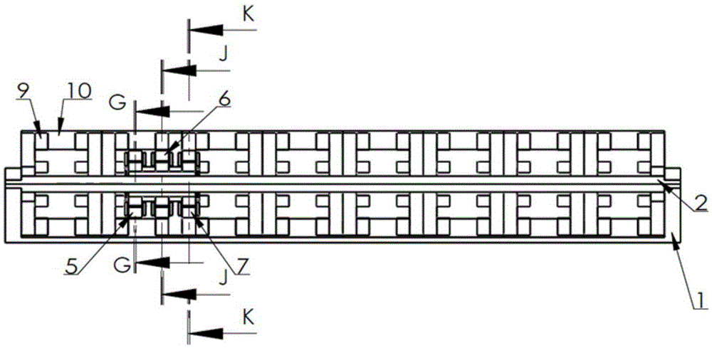
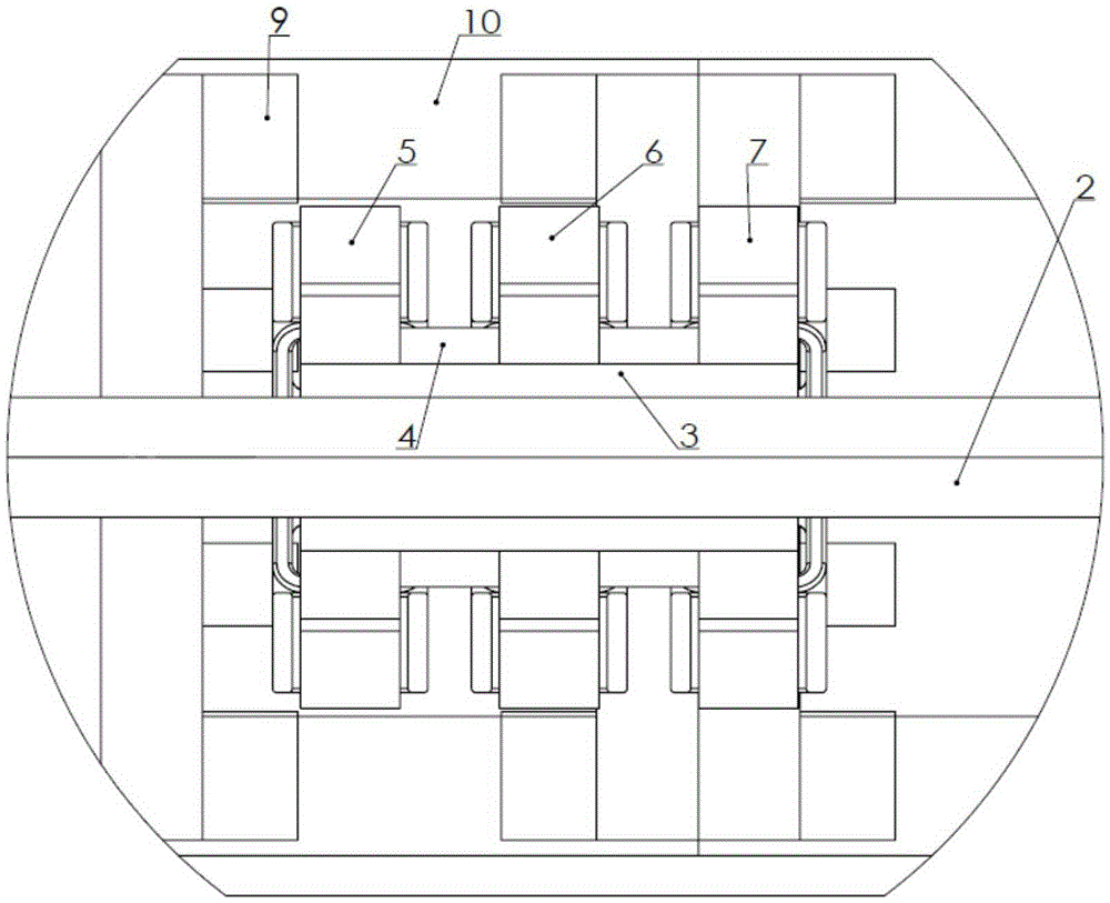
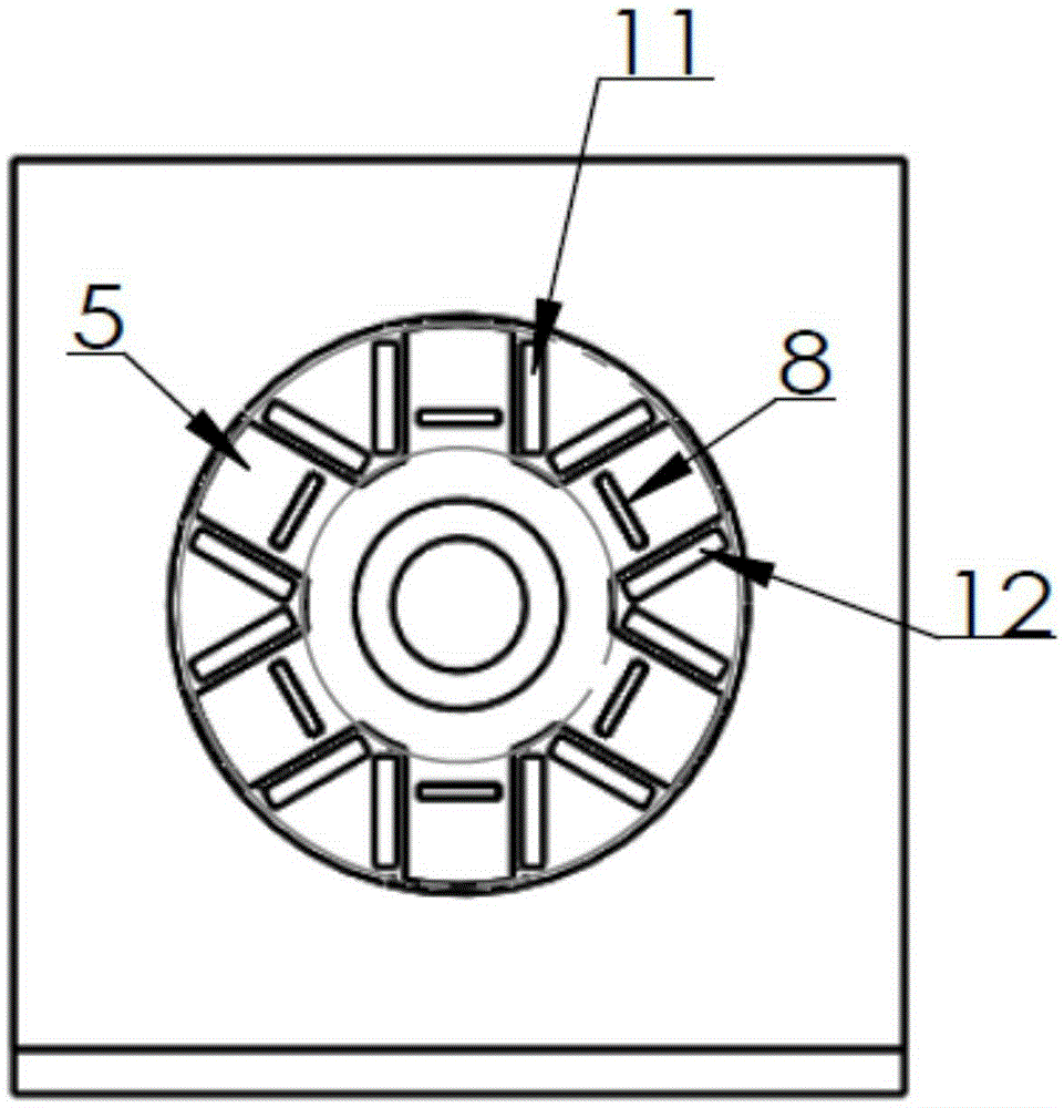
[0024] In this embodiment, the motor operates as an electric motor, the number of phases is 3, the number of stator blocks per cycle in the axial section is 2, and the number of mover blocks is 3. refer to figure 1 , figure 2 , image 3 , Figure 4 and Figure 5 . This embodiment includes a base 1, a shaft 2, a bearing 3, a shaft coupling 4, a stator, a mover, a permanent magnet 8 and mover windings arranged on the mover group. The stator includes several stator blocks 9 and stator sleeves 10, the stator blocks 9 are arranged at equal intervals in the axial direction, and include stator teeth, stator slots and stator yokes, and the stator sleeve 10 consists of several sleeves of the same size The sleeves are connected in the axial direction, and two stator blocks can be fixed in each sleeve; the mover is composed of mover one 5, mover two 6, mover three 7, permanent magnet 8 and mover windings (including A, B, C three-phase) structure, mover 1 5, mover 2 6, mover 3 7 ar...

Embodiment 2

[0029] The motor of this embodiment operates as a generator, and the specific structure is the same as that of Embodiment 1. During the operation of the generator, the DC excitation voltage is directly provided by the permanent magnet. figure 2 position, when the prime mover drives the mover to move in the axial direction opposite to the direction of the stator block 9, it overcomes the magnetic pull to do work, and the mechanical energy is converted into electrical energy. In principle, when the prime mover drives the mover to move in the direction shown in the figure, the mover windings output C and A phase currents and A and B phase currents outward in turn, continuously converting mechanical energy into electrical energy output.

[0030] In this embodiment, the number of stator blocks per cycle is 2, and the number of mover blocks is 3. However, in the specific implementation process, it is not limited to this, as long as the general law of pole-slot matching of the swit...


PUM


Abstract

The invention discloses a transverse flux mutual inductance coupling linear switched reluctance motor, and belongs to a novel structure motor. A transverse flux structure is adopted by the transverse flux mutual inductance coupling linear switched reluctance motor as the linear switched reluctance motor with a novel structure; the utilization rate of a circuit and a magnetic circuit in a system is improved by a coil inductance coupling principle; slot-pole combination is the same as that of a traditional linear switched reluctance motor in the axial section, but a permanent magnet is inlaid on each mover tooth; and the pole number and pole arcs of a stator and a mover are the same in the transverse section, so that the minimum transverse magnetic flux leakage is ensured. Motor windings are concentrated windings; two-phase windings are simultaneously conducted at each moment; and the electrifying order is A+B-, B+C- and C+A-. The power density of the motor is improved by mutual inductance coupling between motor coils; an excitation power supply is omitted by adoption of the permanent magnets; decoupling of the magnetic circuit and the circuit in a geometric structure is ensured by the transverse flux principle; and the transverse flux mutual inductance coupling linear switched reluctance motor is especially suitable for an electromechanical energy conversion occasion of a low-speed, high-thrust and high-power linear motion.

Description

technical field [0001] The invention belongs to a switched reluctance motor in the field of linear motors, and in particular relates to a novel linear switched reluctance motor with mutual inductance coupling of transverse magnetic flux coils. Background technique [0002] The linear motor can directly realize the electromechanical energy conversion of linear motion, eliminating the intermediate conversion mechanism, which can improve the energy conversion efficiency and greatly reduce the system cost. The switched reluctance motor has simple structure, good heat dissipation performance and good fault tolerance, and is an ideal electromechanical energy conversion device. However, the mutual inductance between the windings of the traditional switched reluctance motor is independent, and only one phase is excited at the working time, the work efficiency is low, and the power density of the motor is low. The discontinuous distribution of the internal magnetic field affects the...

Claims


Application Information

Patent Timeline
Patent Type & Authority Applications(China)
IPC IPC(8): H02K41/03H02K16/00
Inventor 杜锦华鲁盼薛运田
Owner XI AN JIAOTONG UNIV
Features
  • R&D
  • Intellectual Property
  • Life Sciences
  • Materials
  • Tech Scout
  • Unparalleled Data Quality
  • Higher Quality Content
  • 60% Fewer Hallucinations
Learn More