Power Factor Adjustment in Multiphase Power Systems

A power factor, multi-phase technology, applied in reactive power adjustment/elimination/compensation, conversion of irreversible DC power input to AC power output, reactive power compensation, etc., which can solve the problem of reactive power consumption by inductors

Active Publication Date: 2017-06-20
TESLA INC
View PDF5 Cites 0 Cited by
  • Summary
  • Abstract
  • Description
  • Claims
  • Application Information

AI Technical Summary

Problems solved by technology

Capacitors are traditionally thought to generate reactive power and inductors consume reactive power

Method used


Image

  • Power Factor Adjustment in Multiphase Power Systems
  • Power Factor Adjustment in Multiphase Power Systems
  • Power Factor Adjustment in Multiphase Power Systems

Examples


Embodiment Construction

[0035] In the following description, various details are set forth for the purpose of explanation. However, one skilled in the art will recognize that the present invention may be practiced without these specific details. In other instances, well-known structures and devices are shown in block diagram form in order not to obscure the description of the present invention in unnecessary detail.

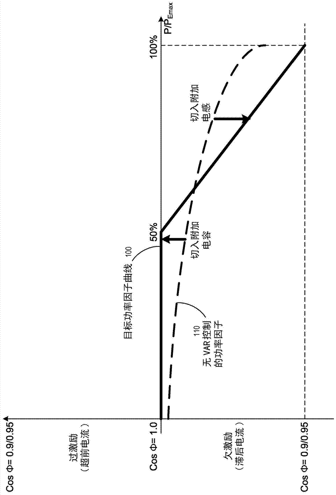
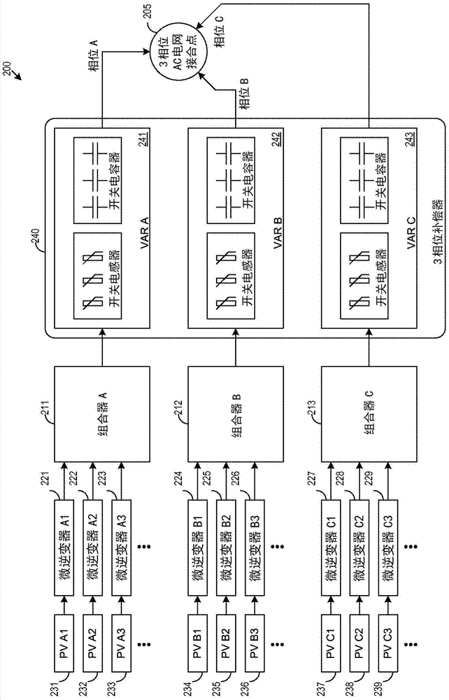
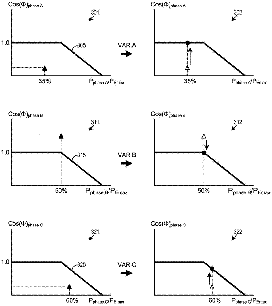
[0036] Some embodiments of the present invention provide a multiphase power generation system for renewable energy sources in which reactive elements (ie, capacitors and / or inductors) can be selectively switched in and out to meet specific power factor requirements. In some embodiments, each phase of a multiphase power system receives power generated from a set of inverters, and each phase has a set of switched reactive elements for controlling said particular phase belonging to the multiphase system A power factor adjustment is made to the power produced by a set of inverters. In som...


PUM


Abstract

A multi-phase power generation system (200) for renewable energy is provided wherein reactive elements (ie capacitors and / or inductors) can be selectively switched in or out to meet specific power factor requirements. Each phase (A, B, C) of the multi-phase power system (200) receives generated power from a bank of inverters (221-229), and each phase (A, B, C) has A switching reactive element group (241-243) for adjusting the power factor of the power generated by the inverter group (221-229). The power outputs of the inverter groups (221-229) belonging to a particular phase (A, B, C) are combined into one combined AC power output and passed through the group of switched reactive elements ( 241-243) to perform power factor adjustment for that particular phase (A, B, C) on the combined power output. In some embodiments, at least some of the inverters (221-229) are micro-inverters that convert DC power from one or both solar panels (231-239) to AC power.

Description

[0001] Claims of benefits of earlier application [0002] This application claims the benefit of US Provisional Application 61 / 812,694, filed April 16, 2013, which is incorporated herein by reference. Background technique [0003] In power transmission and distribution, volt-ampere reactive (VAR) is a unit used to measure reactive power in an AC power system. Reactive power exists in an AC circuit when the current and voltage do not change at the same time. VAR power refers to the imaginary component of the total power supplied by the power generation system due to driving the reactive load so that the current and voltage are out of phase with each other. Driving an inductive load causes the current to lag the voltage, and for a capacitive load it causes the current to lead the voltage. [0004] Therefore, the reactive component of the power can be compensated by adding capacitance / inductance as required. The degree of reactive power is indicated by the displacement power f...

Claims


Application Information

Patent Timeline
Patent Type & Authority Patents(China)
IPC IPC(8): H02J3/18
CPCH02J3/18H02J3/38Y02E40/30H02M7/44
Inventor 保罗·加里蒂艾伦·M·章格瑞斯
Owner TESLA INC
Why Eureka
Try Eureka