
An artificial muscle device

A technology of artificial muscles and ropes, which is applied in the field of artificial muscles, can solve the problems of limited use environment, difficult control, and no consideration of parallel elastic units, etc., and achieve good transmission flexibility and safety, overall simple structure, and convenient and quick adjustment.

Active Publication Date: 2017-07-11
HARBIN ENG UNIV
View PDF1 Cites 0 Cited by
  • Summary
  • Abstract
  • Description
  • Claims
  • Application Information

AI Technical Summary

Problems solved by technology

Currently commonly used artificial muscles are divided into pneumatic artificial muscles and intelligent material artificial muscles, but these two types of artificial muscles also have certain defects: although pneumatic artificial muscles are flexible and can generate sufficient driving force, their elongation is limited , Intrinsic nonlinearity is obvious, control is difficult, the use of airflow is noisy, and the usable environment is limited; intelligent material artificial muscles have the characteristics of light weight, high power density, and high deformation accuracy, but depending on the material, it will bring slow response and deformation Too much force, small deformation, poor environmental friendliness, etc.
However, there are not many published documents on artificial muscles invented based on the Hill muscle mechanics model.
Patent application number 201410424839.8 discloses an artificial muscle based on the Hill two-element mechanical model, which connects a damping contraction unit and an elastic unit in series to simulate human muscles, but it does not consider parallel elasticity unit, so the device is not biomimetic to muscles

Method used


Image

  • An artificial muscle device
  • An artificial muscle device
  • An artificial muscle device

Examples


Embodiment Construction

[0021] The following examples describe the present invention in more detail.

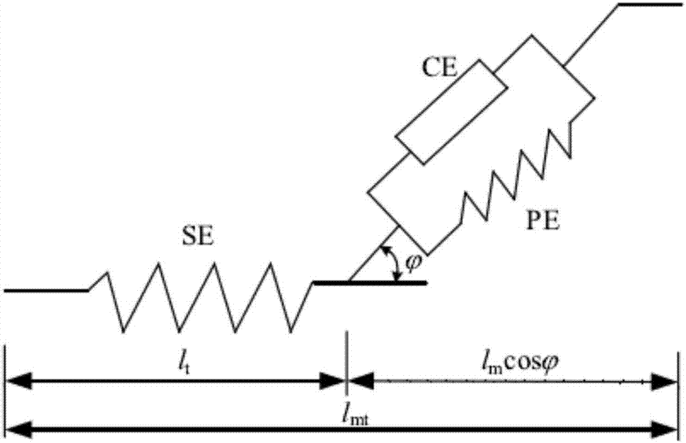
[0022] combine figure 1 , the structural form of the artificial muscle of the present invention is: a parallel elastic unit PE and a contraction unit CE form a parallel structure, and combine with a serial elastic unit SE to form an artificial muscle device composed of Hill three elements, the length of the artificial muscle l mt is the length of the series elastic unit l t and contracted original length l m The sum projected along the length of the muscle, that is in For the muscle feathery horns. considered in this invention So the length of the muscle is l mt = l t +l m .

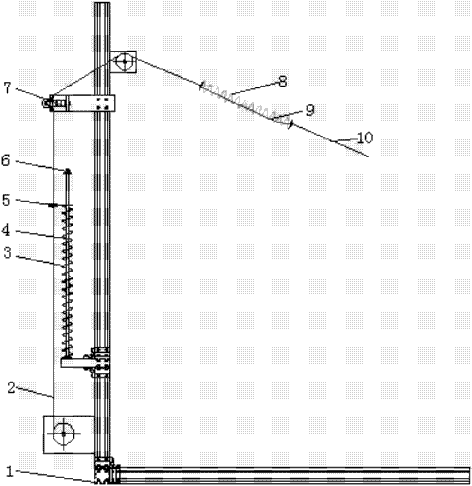
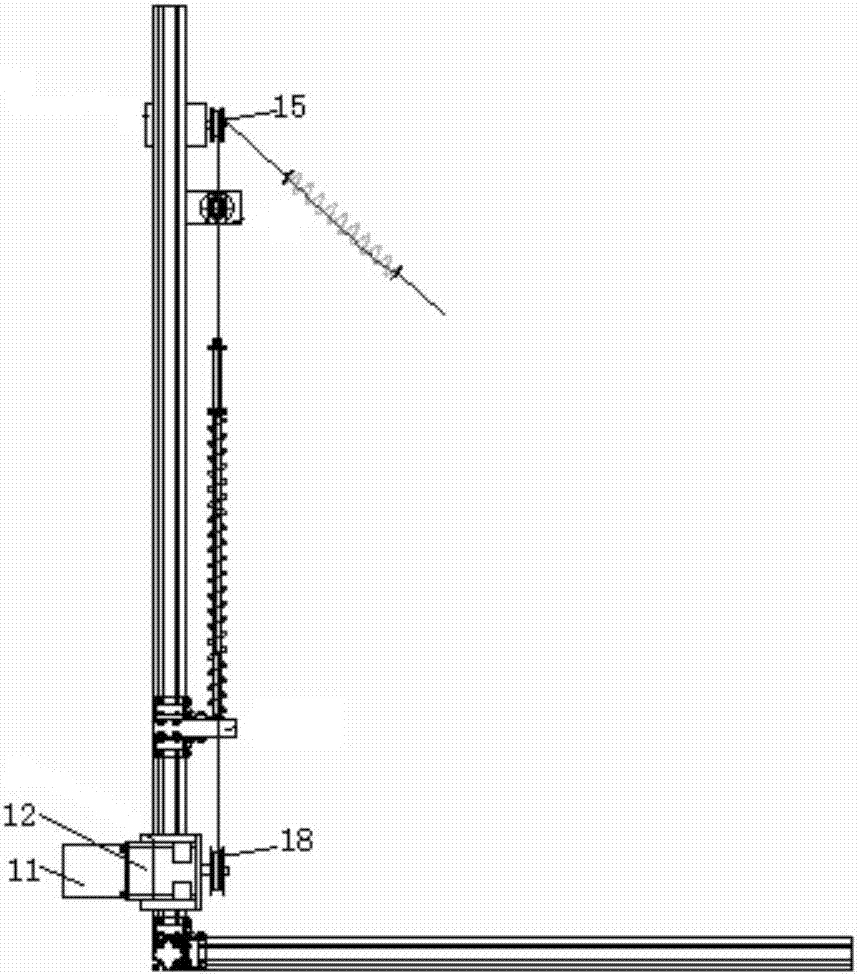
[0023] combine Figure 2-3 , The composition of the artificial muscle system of the present invention includes: a frame 1 as a support system, a flexible cable driving device, a first spring with selectable stiffness, a second spring with selectable stiffness, a guiding and limiting device, and a detection device...


PUM


Abstract

The invention provides an artificial muscle device. The artificial muscle device comprises a machine frame, a flexible cable driving device, a tension sensor and an encoder, wherein the flexible cable driving device comprises a motor, a first flexible cable, a second flexible cable, a flexible cable traction wheel, a first spring and a second spring, the motor and the tension sensor are installed on the machine frame, and the flexible traction wheel is installed on an output shaft of the motor; one end of the first flexible cable is fixed to the flexible cable traction wheel, the other end of the first flexible cable penetrates through the tension sensor to be connected to one end of the second spring, and the second flexible cable is connected with the other end of the second spring; one end of the first spring is fixed to the machine frame, the other end of the first spring is connected to the first flexible cable in parallel through a spring parallel connection device, and the optical-electricity encoder is installed on the motor. The artificial muscle device is simple in structure, high in flexibility, light, high in precision, easy to control, high in response speed, stable in performance and high in muscle bionic degree.

Description

technical field [0001] The invention relates to an artificial muscle, specifically an artificial muscle conforming to the Hill muscle mechanics model. Background technique [0002] Muscle is a biologically contractile tissue with the functions of information transmission, energy transmission, waste removal, energy supply, transmission and self-repair. After being stimulated by the motor nerve signal, it will contract to generate muscle force and drive the bone to move. It does not need a reduction device and a transmission element. It is a one-way force device, and the movement form is linear reciprocating. It has always been the source of inspiration for researchers to develop drives, and human beings have long been committed to the research of biological muscles. The Hill muscle model is a typical representative of human research work. The Hill muscle model is a description of the macroscopic mechanical properties of muscles. This model and its modified model are widely u...

Claims


Application Information

Patent Timeline
Patent Type & Authority Patents(China)
IPC IPC(8): B25J9/10
CPCB25J9/104B25J9/1075
Inventor 王克义赵文艳吴博松冯超王岚
Owner HARBIN ENG UNIV
Learn More