Rotor structure for servo motor

A rotor structure and servo motor technology, applied in the field of servo motors, can solve the problems of motor stator and rotor air gap increase, high machining accuracy, waste of magnetic energy, etc., reduce force transmission parts, improve reliability, and simple structure Effect

Inactive Publication Date: 2016-02-10
褚桂娟
View PDF0 Cites 1 Cited by
  • Summary
  • Abstract
  • Description
  • Claims
  • Application Information

AI Technical Summary

Problems solved by technology

At the same time, the tile-type magnetic steel sheet needs to be glued to the outside of the rotor core with glue alone, and its production, processing and installation accuracy requirements are very high. , when the servo motor rotates at high speed, the magnetic steel sheet on the rotor surface is subjected to a large centrifugal force. When the centrifugal force is greater than the adhesive force of the magnetic steel sheet relative to the rotor core, the magnetic steel sheet will fly away from the rotor, causing the servo Serious damage to the motor
If the magnetic steel sheet protection device is used, it will occupy the air gap space between the stator and the rotor, resulting in an increase in the air gap between the stator and the rotor of the motor, reducing the strength of the armature reaction, limiting the high-speed range of the motor, wasting magnetic energy, and causing material damage. cost increase
[0003] In the prior art, the connection method between the servo motor and the gearbox is to install a coupling at the shaft extension of the motor to connect to the inner gear of the gearbox, and the gearbox also needs a matching coupling to be used in conjunction with the motor coupling. The use of the shaft device requires high machining accuracy. With the long-term high-speed rotation of the servo motor, the connection between the coupling and the shaft extension will become loose and worn, which will affect the speed regulation and adjustment of the servo motor. Torque Accuracy

Method used


Image

  • Rotor structure for servo motor
  • Rotor structure for servo motor
  • Rotor structure for servo motor

Examples


Embodiment Construction

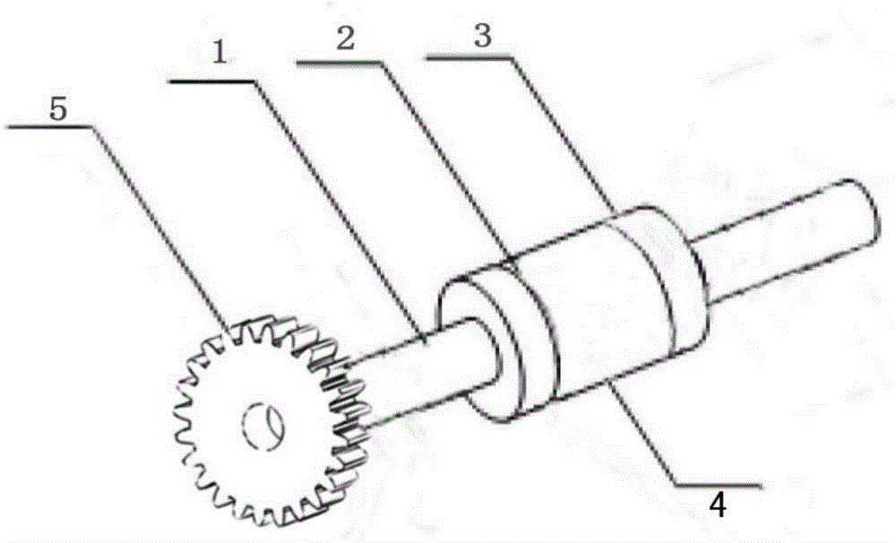
[0015] like figure 1 , figure 2 and image 3 As shown, the rotor structure of the servo motor includes a rotating shaft 1, an iron core 2 arranged on the rotating shaft, a circular permanent magnet 4 fixed around the iron core, and the shaft extension of the rotating shaft has a gear 5; the rotating shaft 1, the rotor core 2, The gears 5 are all made of 316L alloy material with excellent mechanical performance and moderate magnetic permeability, and the ring permanent magnet 4 is made of NdFeB material.

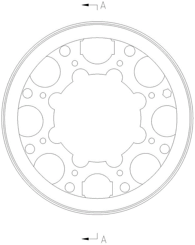
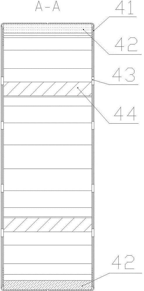
[0016] In this embodiment, the annular permanent magnet 4 is an annular permanent magnet composed of four independent magnets. like figure 2 As shown, the circular ring permanent magnet 4 is respectively provided with a rotor protective cover 41, a magnetic steel 42, a rotor rivet 43, and a silicon steel sheet 44 from outside to inside. The annular permanent magnet 4 is arranged as a cylindrical magnet, which can reduce the production links of the magnet and reduce the ...


PUM


Abstract

The invention creatively relates to a rotor structure for a servo motor. A rotor comprises a rotating shaft, an iron core and an annular permanent magnet, wherein the iron core is arranged on the rotating shaft; the annular permanent magnet is fixed on the iron core in a surrounding manner; a gear is arranged on a shaft extension of the rotating shaft; an annular groove is formed in the iron core; circular lug bosses are arranged at two edges of the groove; the annular permanent magnet is embedded and fixed into the annular groove of the iron core; the annular permanent magnet comprises two semi-circle rings; symmetrical inner threaded holes are formed in the left side and the right side of each semi-circle ring; the two semi-circle rings are connected into the annular permanent magnet through bolts; and the rotating shaft, the iron core, the groove of the iron core, the lug bosses on the edges of the groove and the gear are integrally processed and molded. The rotor structure for the servo motor is compact and relatively convenient to install and use; the manufacturing process is simplified; the cost is reduced; the reliability is improved; and the service lifetime is prolonged.

Description

technical field [0001] The invention relates to the field of servo motors, in particular to a servo motor rotor structure. Background technique [0002] Servo motors are widely used in many fields due to their high control precision, good torque characteristics, overload capability and good acceleration performance. At present, the servo motor rotor structure in the prior art includes a rotating shaft, a rotor iron core, a magnetic steel sheet and a magnetic steel protection device. The outer side of the magnetic steel sheet is equipped with a protective device for the magnetic steel sheet. The protective device mainly uses certain devices to fix the magnetic steel sheet bonded to the outer side of the rotor core, such as binding the magnetic steel sheet with a fiber belt, or using a metal sleeve to cover the magnetic steel sheet. The outside of the magnetic steel sheet and so on. At the same time, the tile-type magnetic steel sheet needs to be glued to the outside of the ...

Claims


Application Information

Patent Timeline
Patent Type & Authority Applications(China)
IPC IPC(8): H02K1/27
Inventor 禹爱民褚桂娟
Owner 褚桂娟
Why Eureka
Try Eureka