

Drive device
A driving device and driving force technology, applied in transmission control, electromechanical device, control drive, etc., can solve problems such as inability to ensure accuracy, easy deterioration of rotating motor control accuracy, and high temperature
- Summary
- Abstract
- Description
- Claims
- Application Information
AI Technical Summary
Problems solved by technology
Method used
Image

Examples
Embodiment Construction
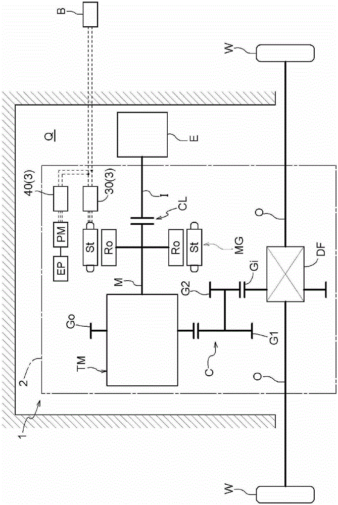
[0048] Embodiments of the driving device of the present invention will be described with reference to the drawings. The drive device 1 of the present embodiment is a vehicle drive device (hybrid vehicle drive device) for driving a vehicle (hybrid vehicle) including both an internal combustion engine E and a rotary electric machine MG as drive force sources for wheels W. Specifically, the drive device 1 is configured as a drive device for a hybrid vehicle of a one-motor parallel system.
[0049] 1. Outline structure of the drive unit
[0050] Such as figure 1 As shown, the driving device 1 includes an input shaft I as an input member drivingly connected to an internal combustion engine E, an output shaft O as an output member drivingly connected to a wheel W, a rotating electric machine MG, and a transmission device TM. In addition, in the present embodiment, the drive device 1 includes a coupling device CL, a gear mechanism G, and a differential gear device DF. The engageme...
PUM
 Abstract
Description
Claims
Application Information