
drive unit

A technology of driving device and control device, which is applied in transmission device control, electromechanical device, control drive, etc., and can solve problems such as easy deterioration of control accuracy of rotating motors, inability to ensure accuracy, high temperature, etc.

Active Publication Date: 2017-12-08
AISIN AW CO LTD
View PDF10 Cites 0 Cited by
  • Summary
  • Abstract
  • Description
  • Claims
  • Application Information

AI Technical Summary

Problems solved by technology

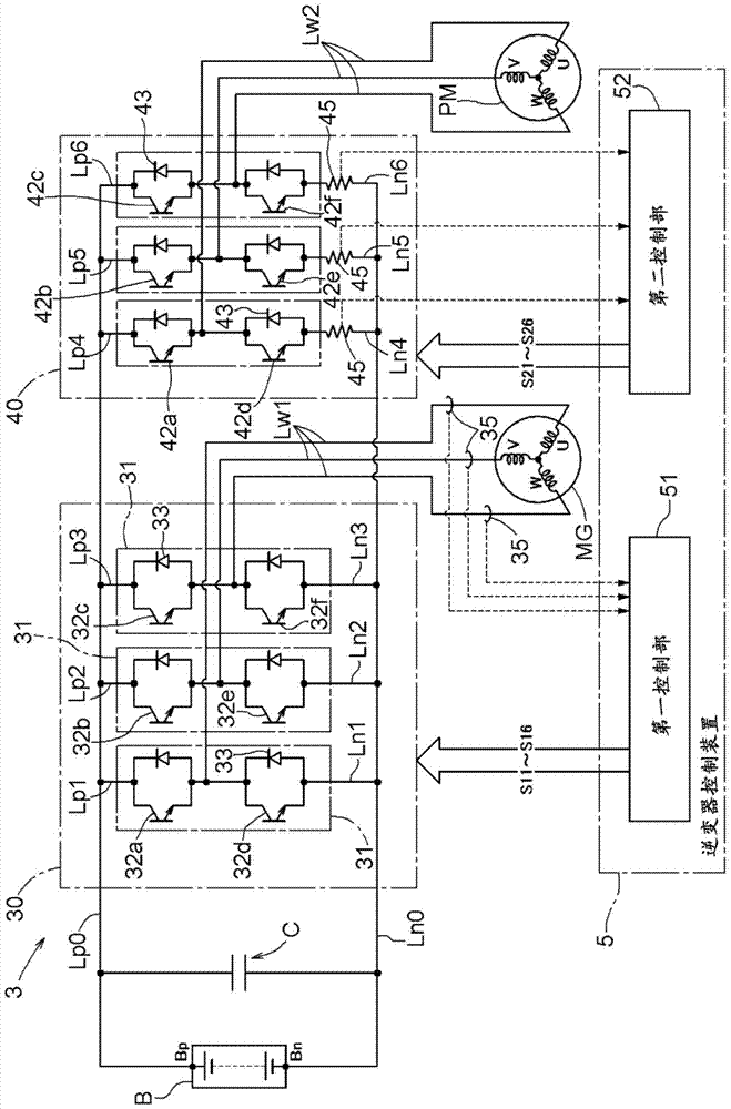
[0004] However, compared with sensors using Hall elements, shunt resistors have poor current detection accuracy and are easily affected by ambient temperature.
Therefore, when shunt resistors are used simply for the purpose of product cost reduction, there is a possibility that the desired accuracy cannot be ensured for the drive control of the rotating electric machine (for example, the motor generators MG1 and MG2 in Patent Document 1). possibility
In particular, considering that the installation environment of the driving device is likely to be considerably higher than the installation environment of general electrical products, the control accuracy of the rotating electrical machine is likely to deteriorate when a shunt resistor is used.

Method used


Image

  • drive unit
  • drive unit
  • drive unit

Examples


Embodiment Construction

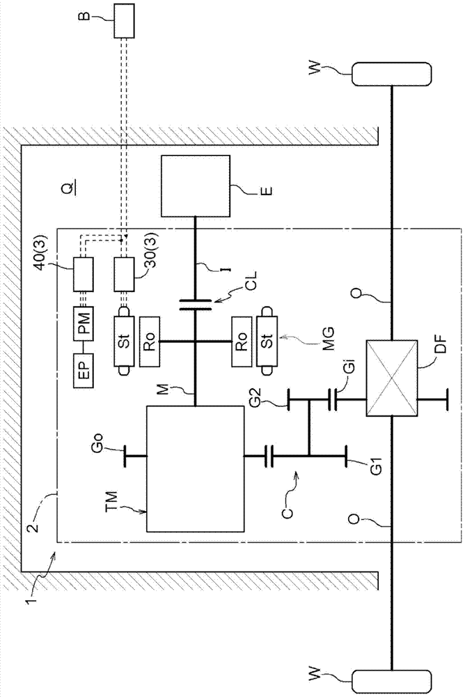
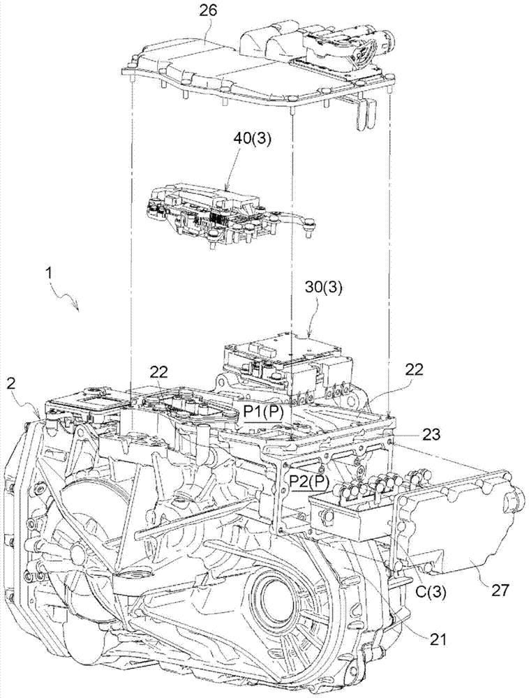
[0052] Embodiments of the driving device of the present invention will be described with reference to the drawings. The drive device 1 of the present embodiment is a vehicle drive device (hybrid vehicle drive device) for driving a vehicle (hybrid vehicle) including both an internal combustion engine E and a rotary electric machine MG as drive force sources for wheels W. Specifically, the drive device 1 is configured as a drive device for a single-motor parallel type hybrid vehicle.

[0053] 1. Outline structure of the drive unit

[0054] Such as figure 1 As shown, the drive device 1 includes an input shaft I as an input member drivingly connected to an internal combustion engine E, an output shaft O as an output member drivingly connected to a wheel W, a rotary electric machine MG, and a transmission device TM. In addition, in the present embodiment, the drive device 1 includes a coupling device CL, a gear mechanism G, and a differential gear device DF. The coupling device ...


PUM


Abstract

The present invention relates to a driving device which suppresses the influence on the control accuracy of a rotating electrical machine to a small degree and reduces product cost. A drive device according to the present invention includes a wheel-driving rotating machine (MG), an AC rotating machine (PM), a first inverter (30), and a second inverter (40). The drive device includes a current sensor (35) for detecting a current flowing to a wheel-driving rotary electric machine (MG), and a shunt resistor (45) for detecting a current flowing to an inverter (40). The proportion ratio of the detectable current period of the current sensor (35) with respect to the control cycle of the first inverter (30) relative to the detectable current of the shunt resistor (45) with respect to the control cycle of the second inverter (40) The proportion is high during the period.

Description

technical field [0001] The present invention relates to a drive device including a rotating electrical machine and an inverter connected between the rotating electrical machine and a DC power supply. Background technique [0002] As a drive device as described above, a device described in JP 2007-166803 A (Patent Document 1) is known. In such an apparatus, in order to perform drive control of the rotating electrical machine [motor generators MG1, MG2], it is necessary to install a current sensor for detecting the current flowing to the stator coil of each phase. Conventionally, as a current sensor used in a driving device, as shown in Patent Document 1, a sensor using a Hall element is common. Sensors using Hall elements have relatively stable temperature characteristics and can detect current with high precision. Therefore, they are frequently used to enable high-precision drive control of rotating electric machines in drive devices that are prone to high-temperature envir...

Claims


Application Information

Patent Timeline
Patent Type & Authority Patents(China)
IPC IPC(8): H02P6/18H02P5/74B60L15/02H02P27/06H02M7/00H02M7/5387H02M7/5395
CPCH02M7/48H02P5/74H02P27/06B60L15/025H02M7/003H02M7/53871H02M7/5395H02P6/18Y02T10/64H02M1/0009H02K11/27H02K11/33B60W10/08B60W10/30F15B11/08F15B2211/20515F15B2211/2053F16H61/0031F16H61/0265H02K5/22H02K11/0094H02P6/14H02P27/08H02M7/53875
Inventor 中尾惠子岩月健
Owner AISIN AW CO LTD
Learn More