A positionable pre-punching rivetless constant temperature stamping die and its control method

A stamping die and control method technology, applied in the field of pre-punching rivetless constant temperature stamping die and its control, can solve the problems of large differences in melting point and thermal expansion coefficient, difficult precise positioning of punches and pre-punching holes, and difficult welding joints, etc. , to achieve the effect of unaffected riveting accuracy, simple implementation and high tensile strength

Inactive Publication Date: 2017-03-29
JILIN UNIV
View PDF6 Cites 0 Cited by
  • Summary
  • Abstract
  • Description
  • Claims
  • Application Information

AI Technical Summary

Problems solved by technology

[0004] One of the purposes of the present invention is to solve the problem that in the prior art, when dissimilar metals such as steel and aluminum alloy are spot welded, due to the large difference in melting point and thermal expansion coefficient, hard and brittle metal compounds appear in the solder joints during welding, and it is difficult to achieve effective welded joints. The problem
[0005] The second purpose of the present invention is to solve the problem of difficult precise positioning between the punch and the pre-punched hole in the prior art

Method used


Image

  • A positionable pre-punching rivetless constant temperature stamping die and its control method
  • A positionable pre-punching rivetless constant temperature stamping die and its control method
  • A positionable pre-punching rivetless constant temperature stamping die and its control method

Examples


Embodiment

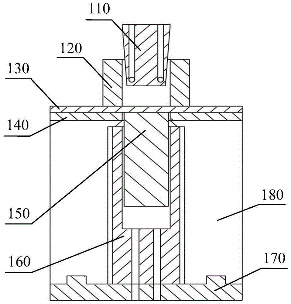
[0050] During the hot forming process of the high-strength steel plate 140, a circular through hole with a diameter of 10mm is punched out at the riveting position of the steel plate.

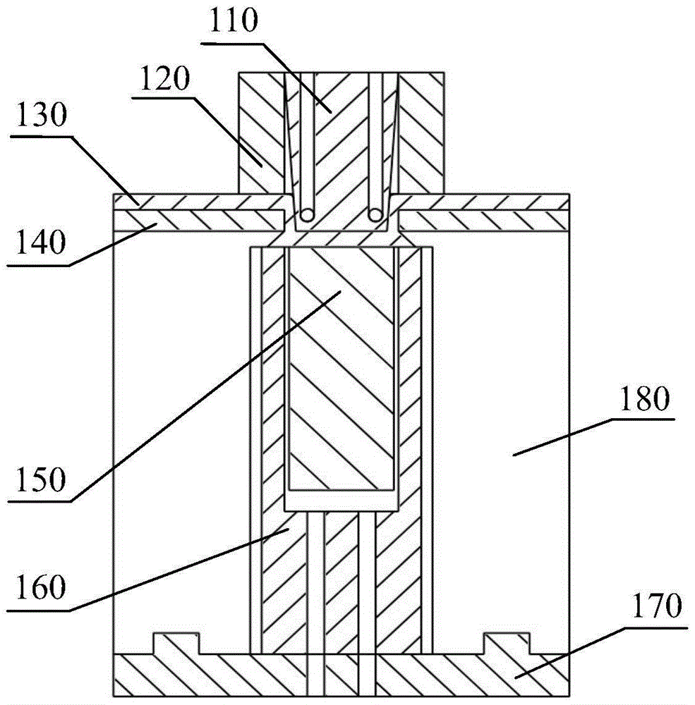
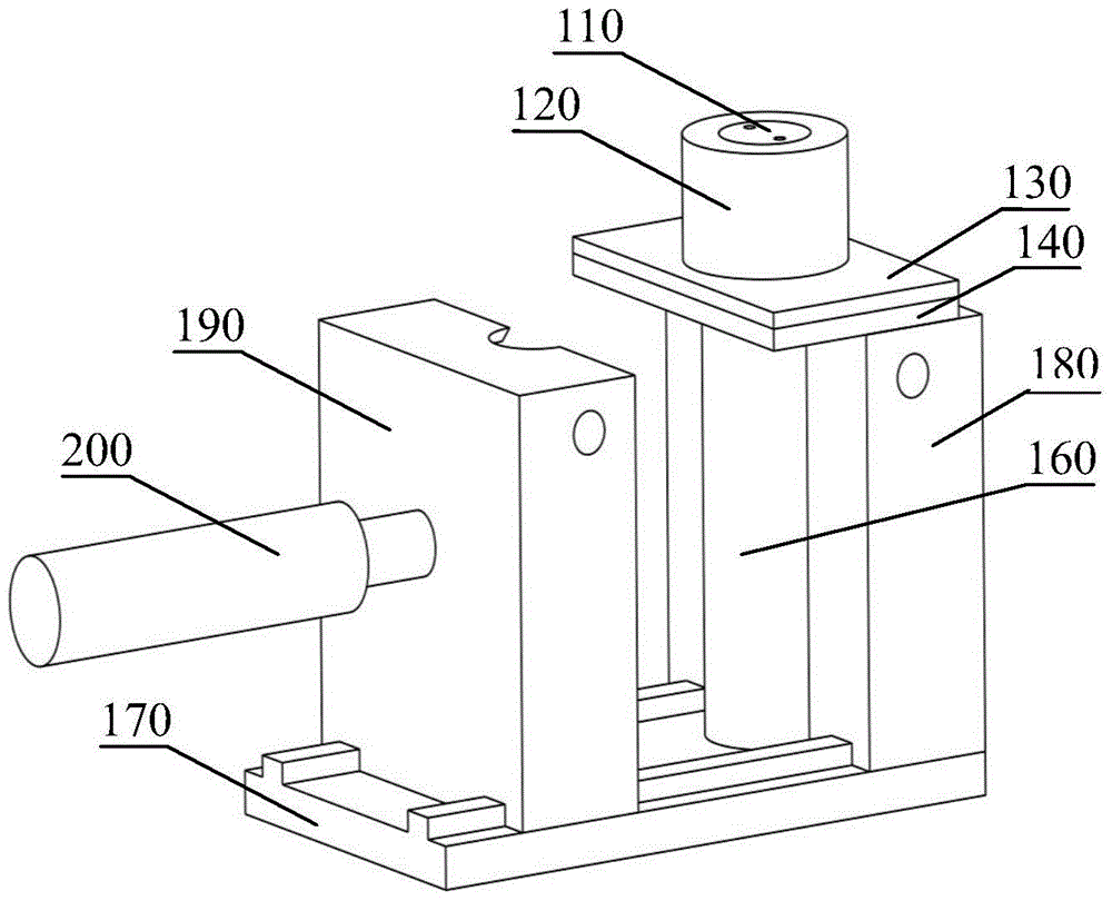
[0051] like figure 1 As shown, the punch 110, the positioning hydraulic cylinder and the integral lower die base are coaxially arranged, and the positions of the hydraulic cylinder and the fixed lower die base 180 are fixed; The diameter of the small circle on the surface is 8mm, the inclination angle of the bus bar is 45°, the height is 15mm, the diameter of the internal cooling liquid channel is 2.5mm, and the distance between the axis plane and the lower surface of the punch is 3mm. The punch 110 is placed in the center hole of the blank holder 120 for sliding connection. The blank holder 120 is a ring-shaped structural member with a height of 15mm, an outer diameter of 20mm, an inner diameter of 10mm, and a piston 150 with a diameter of 10mm. The cylinder 160 has a diameter of 14 mm and a ...


PUM

PropertyMeasurementUnit
diameteraaaaaaaaaa
lengthaaaaaaaaaa
heightaaaaaaaaaa

Abstract

The invention discloses a pre-hole-punching rivet-free constant-temperature stamping die capable of performing positioning. The stamping die comprises a punch, a lower die holder and a hydraulic cylinder. The punch is of a circular truncated cone structure. The radius of the upper surface of the punch is larger than that of the lower surface of the punch. The center of the lower die holder is a containing cavity. The upper portion of the containing cavity is a regular circular truncated cone cavity, and the lower portion of the containing cavity is provided with a through hole. An upper end opening of the regular circular truncated cone cavity is formed in the upper plane of the lower die holder, and the lower end of the regular circular truncated cone cavity is communicated with the through hole. The hydraulic cylinder is located in the through hole. A piston of the hydraulic cylinder stretches out of the upper end opening of the regular circular truncated cone cavity in the non-stamping process. The punch and the lower die holder are both provided with a cooling channel and are provided with a temperature sensor and a controller. The invention further discloses a control method of the pre-hole-punching rivet-free constant-temperature stamping die capable of performing positioning. The pre-hole-punching rivet-free constant-temperature stamping die capable of performing positioning achieves connection between high-strength steel and aluminum alloy without rivets and has the advantages that accurate positioning can be achieved, and meanwhile riveting accuracy is not affected due to the cooling punch and the die.

Description

technical field [0001] The invention relates to the field of rivetless stamping dies, in particular to a positionable pre-punching rivetless constant temperature stamping die and a control method thereof. Background technique [0002] In order to pursue the lightweight of the body, without changing the body specifications, the weight of the body structure can be realized by optimizing the body structure, updating the manufacturing and connection process of body parts, and replacing traditional low-strength steel with lightweight materials. High-strength steel has the advantages of high weight reduction potential, high collision absorption energy, high fatigue strength, high formability and low plane anisotropy, and aluminum alloy has the advantages of light weight, corrosion resistance, high specific strength, easy processing, beautiful surface and recycling cost low merit. Therefore, a large number of high-strength steels and aluminum alloys have been widely used in the ca...

Claims


Application Information

Patent Timeline
Patent Type & Authority Patents(China)
IPC IPC(8): B21D37/10B21D37/16B21C51/00B21D39/03
CPCB21C51/00B21D37/10B21D37/16B21D39/034
Inventor 庄蔚敏杨冠男解东旋敖文宏刘西洋徐纪栓闫雪燕张凯希李冰娇胡哲
Owner JILIN UNIV
Why Eureka
Try Eureka