
A pressing device suitable for LED lamp heat sink and its realization method

A pressing device and LED lamp technology, applied in metal processing, metal processing equipment, manufacturing tools, etc., can solve the problem of only pressing one group or two groups at a time, and achieve high safety, reasonable power design, and low cost Effect

Active Publication Date: 2017-12-12
HENGDIAN GRP TOSPO LIGHTING
View PDF5 Cites 0 Cited by
  • Summary
  • Abstract
  • Description
  • Claims
  • Application Information

AI Technical Summary

Problems solved by technology

Since it is necessary to apply a large pressure to ensure the quality of the pressing during pressing, it is generally completed with a cylinder with a large bore diameter. If multiple groups are pressed together, there must be enough space to place these cylinders, so manual feeding or automatic feeding is generally used. The combined equipment can only press one group or two groups at a time.

Method used


Image

  • A pressing device suitable for LED lamp heat sink and its realization method
  • A pressing device suitable for LED lamp heat sink and its realization method

Examples


Embodiment 1

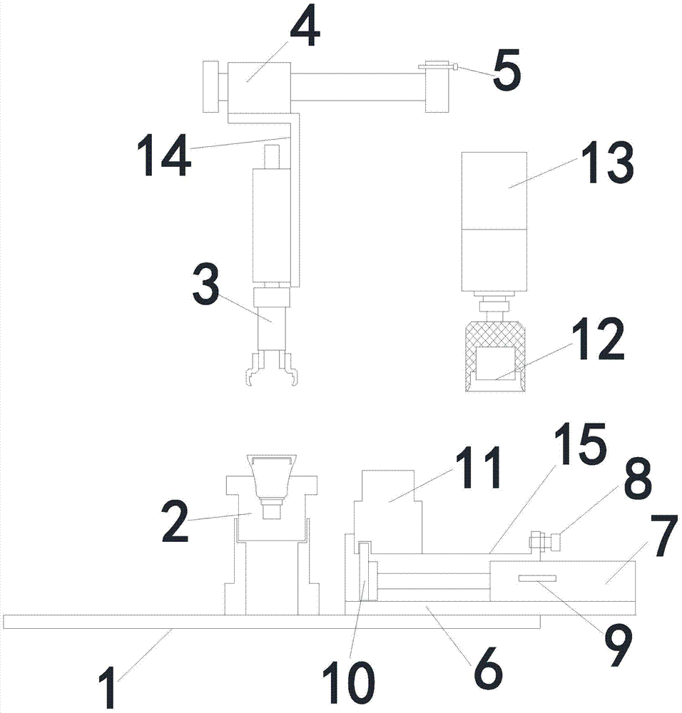
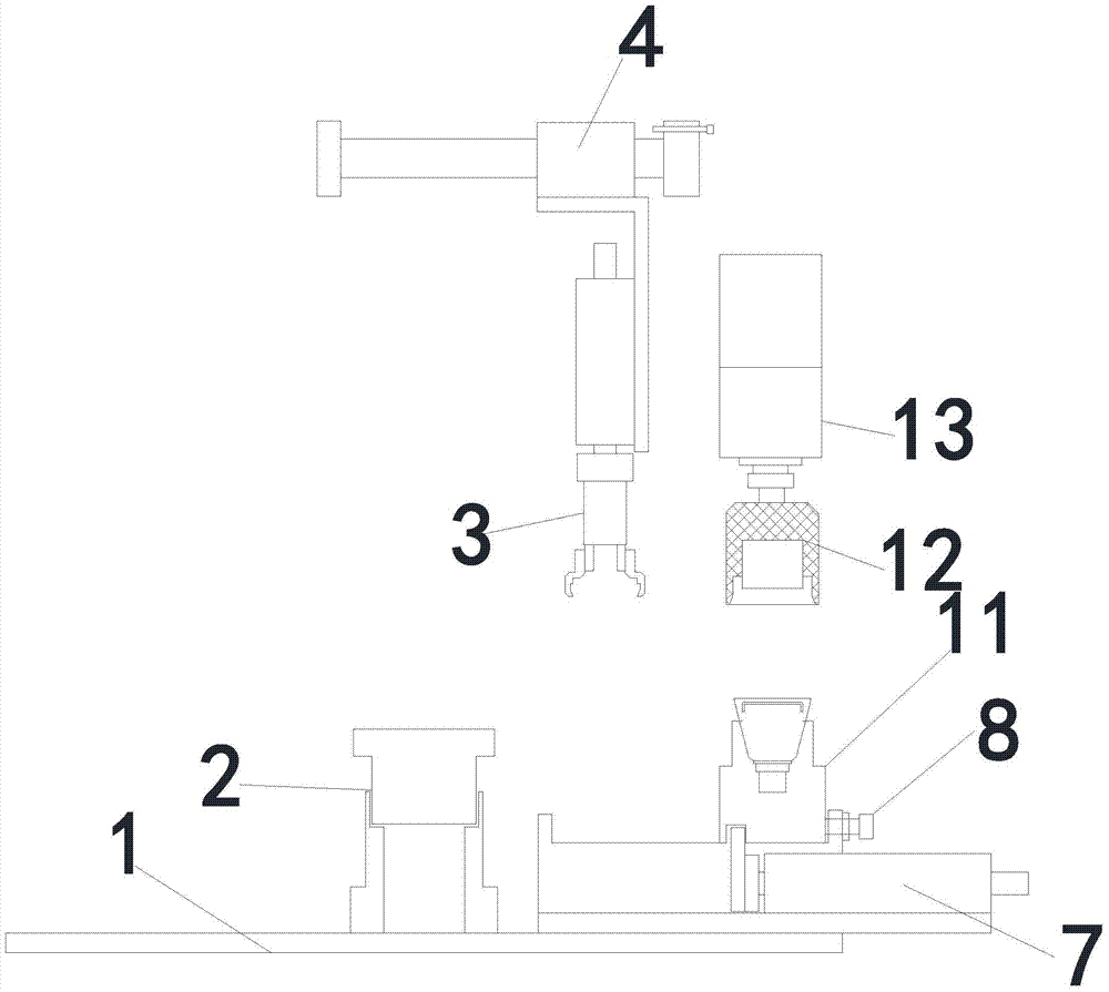
[0039] Such as Figure 1~2 As shown, a pressing device suitable for heat sinks of LED lamps includes an automatic conveyor belt, on which several carriers are arranged, and an execution cylinder is installed on the side plate of the automatic conveyor belt to block and release the carriers. There is a manipulator, and the manipulator is connected with the cylinder of the slide table. The end of the cylinder of the slide table is provided with a first limit screw. There is a second limit screw, and a position sensor is installed on the side of the moving cylinder. The telescopic end of the moving cylinder is connected to the short plate. The head of the short plate goes deep into the groove under the supporting fixture. Tool, the lower pressure fixture is connected with the force cylinder.

[0040] The carrier in this embodiment is a five-connected carrier; the slide cylinder is connected to the manipulator through the manipulator connecting plate.

[0041] This embodiment al...

Embodiment 2

[0059] The difference between this embodiment and Embodiment 1 lies in that the length of the head of the short plate in this embodiment is 12 mm, and the depth of the groove is 12.5 mm.

Embodiment 3

[0061] The difference between this embodiment and Embodiment 1 is that the length of the head of the short board in this embodiment is 10mm, and the depth of the groove is 10.5mm


PUM


Abstract

The invention discloses a heat sink pressing device suitable for an LED (light-emitting diode) lamp. The heat sink pressing device comprises an automatic conveyor belt, wherein a plurality of carriers are arranged on the automatic conveyor belt; the side plate of the automatic conveyor belt is provided with an implementation air cylinder for blocking and releasing the carriers; a mechanical hand is arranged above the conveyor belt; the mechanical hand is connected with a sliding table air cylinder; the end part of the sliding table air cylinder is provided with a first limiting bolt; a pressing fixing plate is arranged below the side of the sliding table air cylinder; a carrying air cylinder is arranged on the pressing fixing plate; a second limiting bolt is arranged on the carrying air cylinder; the side of the carrying air cylinder is provided with a position sensor; the telescopic end part of the carrying air cylinder is connected with a short plate; the head part of the short plate penetrates into a groove below a supporting jig; a pressing jig is arranged above the supporting jig; and the pressing jig is connected with a booster air cylinder. The invention further discloses an implementation method suitable for the heat sink pressing device for the LED lamp. The heat sink pressing device has the characteristics such as a simple structure, low manufacturing cost, high production efficiency, low labor intensity, good product quality, high degree of automation, high safety and the like.

Description

technical field [0001] The invention relates to lamp production technology, in particular to a pressing device suitable for heat sinks of LED lamps and a realization method thereof. Background technique [0002] The non-LED used to replace the traditional lighting source is none other than the popular product represented by the A60 lamp. At this stage, the structural forms of A60 lamps are basically the same, mass production has become the norm, and the heat sink is an important production link. The heat dissipation capacity of the lamp directly affects the service life of the product. Whether the heat sink and the lamp housing can meet the design requirements depends on the production method of the process of pressing the heat sink, and the production efficiency is the key factor affecting the product cost. [0003] In order to ensure the reliability of heat conduction, the design adopts the tight fit method of heat sink and lamp housing interference fit. In production, sp...

Claims


Application Information

Patent Timeline
Patent Type & Authority Patents(China)
IPC IPC(8): B23P19/027B23P19/00
CPCB23P19/001B23P19/007B23P19/027
Inventor 张志钢
Owner HENGDIAN GRP TOSPO LIGHTING
Learn More